
This post discusses the significance of regulating starting current & torque while starting a motor. There are various methods for starting a three-phase induction motor. In this post, however, a star-delta method using PLC (programmable logic controller ) can be used to start the Induction Motor.
Star Delta Starter
In the 50Hz frequency power using industry, star/delta starters are potentially the most prominent reduced voltage starters. It is commonly referred to as Wye/Delta starters at the 60Hz frequency. They are used for the purpose of reducing the starting current provided to the motor at startup in order to reduce the supply voltage.
The Star/Delta Starter is a highly common type of starter that is widely used in comparison to other types of induction motor starting methods. A cage motor with a delta-connected stator winding is referred to as a star delta.
What is Star Delta in PLC?
This is a start method that reduces both starting current and torque. A typical star delta starter design includes 3 contactors, an overload relay (or) circuit breaker, and a timer to set the time in the star position.
Hardware Requirements
1). Induction Motor
3). Contactor
4). SMPS
5). MCB
6). PLC
SMPS
SMPS (Switched Mode Power Supply) uses a switching regulator to efficiently convert electrical power. SMPSs, like other power supply, transport power from a source such as mains power to the load like a computer. Varying ON-to-OFF time regulates voltage. A switched-mode power supply’s power conversion efficiency is crucial. Due to the decreased transformer size and weight, SMPS can be much smaller and lighter than linear supplies. When efficiency, size, or weight are needed, switching regulators replace linear regulators. However, their switching currents can create electrical noise and inadequate systems may have a poor power factor.
MCB
Low-voltage electrical networks use MCB’s (Miniature Circuit Breaker) instead of fuses. Miniature circuit breakers have manual opening and shutting mechanisms. It’s “ON,” “OFF,” and “TRIPPED.” If the MCB trips due to overcurrent, the external switching latch can be “TRIPPED”. The switching latch is “OFF” while manually turning off the MCB. MCB switches are “ON” when close. MCBs can be closed, tripped, (or) manually switched off by examining the switching latch.
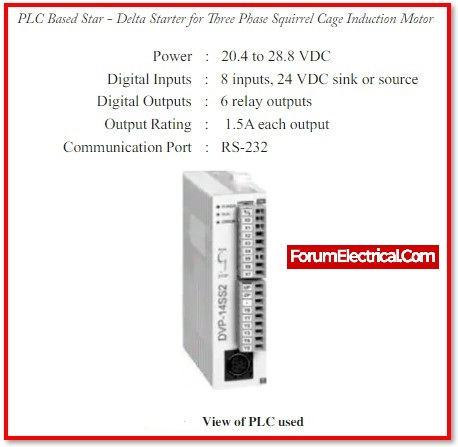
PLC
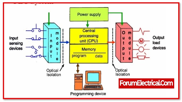
The slim type PLC includes the core sequential control functionalities of the DVP-SS series PLC, with faster execution speed and increased real-time monitoring capability.
The various stages are outlined below.
1. Input Scan, which detects the status of all input devices connected to the PLC.
2. Programme Scan, which executes user-created programme logic.
3. Output Scan activates or deactivates all output devices linked to the PLC.
4. Maintenance which includes the communications with the programming terminals and internal diagnostics.
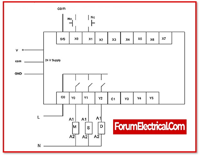
Connection (Wiring) of a 3-phase motor to a PLC
In star-delta starter, the motor first runs in star connection for a few minutes as if it is star-delta, after sufficient speed has been developed, the connection is made Delta. Star connection – here the current that the motor draws is one third of the rated current.
So by starting the motor in star connection we reduce the starting current.
Working principle of PLC based Star-Delta Starter
The functioning technique is as follows.
1. Connect the 24-volt DC SMPS to a three-phase power supply. To measure the linecurrent, a multimeter is connected.
2. Connect contactors to the induction motor’s stator windings. The windings connections will need to be inserted into the induction motor’s connecting box. The stator should be attached in a WYE configuration.
3. Connect breaker control unit to the tacho-generator.
4. Ensure that the torque knob on the brake unit is set to minimum, i.e., rotate all the way around anticlockwise (CCW).
5. Connect the NO & NC switches to the PLC’s digital input module. Connect one end of each switch to the SMPS’s 24 V and the other end to the matching input sockets on the PLC Basic Unit.
6. Connect PLC output from PLC Basic Unit to contactor outputs Y0,Y1, and Y2. Connect the A2- end of the main contactor to the SMPS’s zero volt.
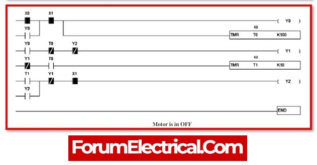
It can be observed in the ladder logic that X0 is generally open (NO), X1 is normally open (NO), timer, and main (Y0). Star (Y1) and Delta (Y2) contactors are employed. WPLsoft is the programme writing, simulation, and execution software.
F1 to F12 provide different functional keys in this software and are accessible. Then develop the ladder logic programme utilising these function keys. F1 indicates generally open in this function keys. Normally closed (F2).
In this programme, F1 & F2 are input variables. F6 contains a variety of functions such as a timer, counter, and so on. In the F6 key, the timerfunction is numbered 96. In this ladder logic, F7 has output variables.
PLC Ladder Logic Program for Star-Delta Starter
Dump the programme into the PLC debugging programme at this point. Switch to internet mode and RUN the program as shown
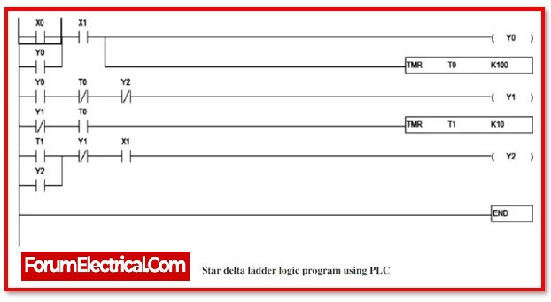
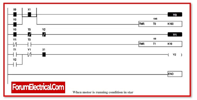
The green colour signifies that they are turned on. Timer 0 is running, and K100 displays the number of milliseconds (milli-sec) it has been running. Y0 is on at the same time that Y1 is on.
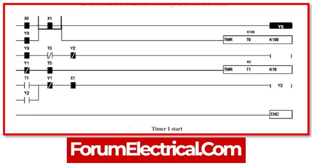
After timer 0 completes its function for 10 seconds (consider K100 as 10 seconds), the Y1 star opens at timer 1 and begins counting time for a delay of 1 second, as shown
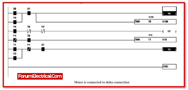
After the delay time, 1sec (consider K10 as 1 second), the motor achieves 80% of its rated speed, and the timer is reset, the motor operates in delta mode.
i.e., Y2 delta contactor, turns ON.
PLCs are used to implement a star-to-delta starter for a three-phase induction motor. Ladder programming is used to construct and programme a prototype hardware model. The starting characteristics of a three-phase induction motor can be regulated more effectively by this user-friendly starter. The ladder diagram programmed uses a timer to control when contactors open and close.
It has been found that PLC programming provides a high level of flexibility because modifications can be made by simply altering the required commands in ladder diagram. PLC has therefore demonstrated its range of applications as a controller and been used to further automation technology.
What is the use of Star Delta connection in Motor?
Star delta starters are a different device that can be utilized to lower current demand during motor initiation. It is commonly used to start three-phase induction motors, although it can only be utilized when the motor is not loaded and the needed starting current is minimal.


