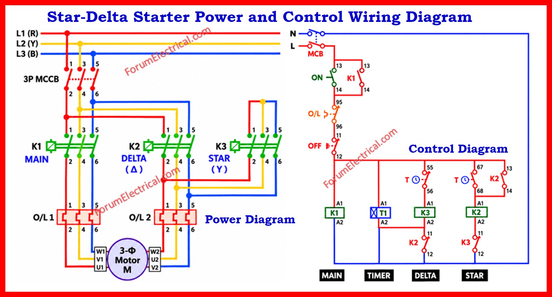
Star-Delta (Y-Δ) Starter
A star-delta (Y-Δ) starter is a widely used reduced-voltage starting method for three-phase squirrel-cage induction motors.
It is suitable where direct-on-line (DOL) starting could produce excessive current, significant voltage dips, or mechanical shock.
During starting, the motor windings are connected in star, and after the motor reaches sufficient speed, the connection changes to delta.
This reduces the starting current and starting torque to approximately one-third of the corresponding DOL values helping to minimize electrical and mechanical stress.
The post discussed here uses three contactors (K1 main, K2 delta, K3 star), a moulded case circuit breaker (MCCB), an overload relay (OLR), an on-delay timer (T1), and Start/Stop push buttons – the standard component set found in virtually every industrial star-delta panel, whether used for pumps, compressors, conveyors, fans (or) general-purpose heavy duty motors.
Primary Components
The table below summarizes the principal components utilized in the circuit, their function and typical rating considerations.
| Component | Function | Typical Rating / Notes |
|---|---|---|
| MCCB (Moulded Case Circuit Breaker) | Provides main short-circuit and overload protection for the entire power circuit | Sized per motor FLC x 1.25 (typical) |
| K1 – Main Contactor | Connects the three main supply lines to the motor stator winding start ends (U1, V1, W1) | AC-3 duty rated |
| K2 – Delta Contactor | Reconfigures the winding ends into a closed delta after the timer elapses | Interlocked with K3 |
| K3 – Star Contactor | Shorts the three winding tails (U2, V2, W2) together to form a star point for starting | Interlocked with K2 |
| OLR – Overload Relay | Monitors motor current continuously and trips the control circuit on sustained overload | Set at motor rated full-load current |
| T1 – Timer (ON-Delay) | Times the star-running period and triggers automatic changeover to delta | Adjustable, typically 5-15 seconds |
| Start / Stop Push Buttons | Manual operator control for energizing and de-energizing the control circuit | NO for Start, NC for Stop |
Power Circuit
The power circuit carries the full motor current (FLC) and is responsible for physically connecting the three-phase supply to the motor windings in the correct configuration at each stage of starting.
Power flows from the incoming three-phase supply through the MCCB which provides short-circuit protection and acts as the main isolating device for the entire panel.
From the MCCB, the three phases are wired in parallel to the main contactor K1 and, through K1, to the overload relay (OLR) and finally to the stator terminals U1, V1 and W1 of the motor.
The remaining 3 winding terminals: U2, V2 and W2 are brought out separately and are switched between the star contactor K3 and the delta contactor K2.
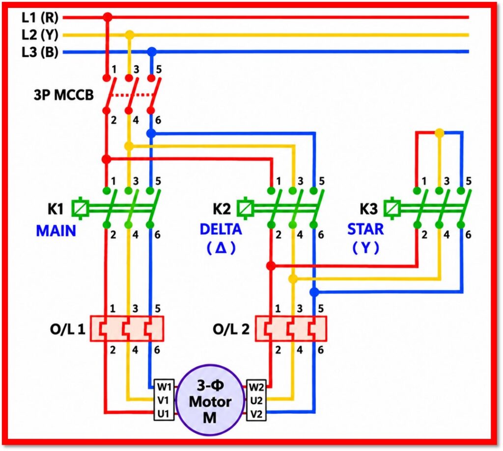
When K3 is closed, terminals U2, V2, and W2 are joined together forming a common star point; this connects the winding in star and reduces the voltage across each phase winding to 1/√3 (about 58%) of line voltage which in turn reduces the starting current to roughly one-third of the DOL value.
When K2 is closed instead, U2 is linked to V1, V2 to W1 and W2 to U1 forming a closed delta loop across the winding and this restores full line voltage across each phase for normal running.
Because K2 and K3 must never be closed at the same time which doing so would short circuit 2 phases of the supply directly through the winding that the power circuit always incorporates mechanical interlocking between the 2 contactors in addition to electrical interlocking in the control circuit.
This dual interlocking is one of the most safety-critical aspects of the star-delta design.
Control Circuit
The control circuit operates at a lower current and is responsible for the logic that energizes the correct contactor coils in the correct order and for the correct duration.
Control voltage is typically derived from two phases of the supply (or from a control transformer) and is fed through the normally closed contact of the OLR and the normally closed Stop push button before reaching the Start push button.
Pressing the Start push button energizes the coil of K1 (through a normally closed auxiliary contact of K2 which serves as an electrical interlock) and simultaneously energizes K3 and the timer T1.
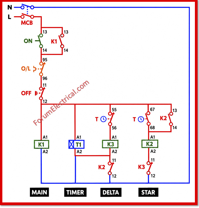
A holding (seal-in) auxiliary contact of K1, wired in parallel with the Start button, keeps K1 latched in once the button is released.
With K1 and K3 both energized, the motor runs in star.
T1 starts timing as soon as it is energized.
When the preset time on T1 elapses, its timed contact operates: a normally closed timer contact opens to de-energize K3 and a normally open timer contact closes to energize K2 (through a normally closed auxiliary contact of K3, providing electrical interlocking in the control circuit as well).
Since K3 must drop out before K2 can pick up, there is a brief, deliberate transition period during which neither star nor delta contactor is closed.
The motor then continues running with K1 and K2 energized placing the winding in delta for full-voltage, full-load operation.
Pressing the Stop push button (or) the OLR tripping on a sustained overload, breaks the control supply to all three contactor coils, immediately de-energizing K1, K2 (or K3), and the timer and bringing the motor to a stop with all power contacts open.
Sequence of Operation
| Stage | Contactors Energized | Winding Configuration | Condition |
|---|---|---|---|
| 1). Standby | None | Open circuit | MCCB ON, control supply available, motor stopped |
| 2). Starting (Star) | K1 + K3 | Star (Y) – reduced voltage per phase | START pressed; timer T1 begins timing |
| 3). Transition | K3 drops out (brief delay) | Momentary open – contactors are interlocked so K2 and K3 are never on together | T1 reaches preset time |
| 4). Running (Delta) | K1 + K2 | Delta (Δ) – full line voltage per phase | Motor runs at full-load torque and speed |
| 5). Stop / Fault | All de-energized | Open circuit | STOP pressed (or) OLR trips on overload |
Interlocking and Protection
- Mechanical interlock between K2 and K3: a mechanical linkage physically prevents both contactors from closing simultaneously, even in the event of a control-circuit fault.
- Electrical interlock between K2 and K3: normally closed auxiliary contacts of each contactor are wired into the other’s coil circuit, so that each can only be energized while the other is de-energized.
- Overload protection: the OLR continuously senses motor current on all three phases and opens the control circuit if current remains above the set threshold for longer than its trip-curve permits, protecting the motor from thermal damage due to overload, single-phasing, or a failed transition.
- Short-circuit protection: the MCCB protects the cabling and components from fault currents and also serves as the main manual isolator for maintenance.
- Timer coordination: T1 is set with enough delay to allow the electrical motor to reach 80-85% of synchronous speed before the transition to delta that is minimizing the current transient that occurs during changeover.
Advantages of the Star-Delta Method
- Reduces the starting current to approximately 1/3rd of the direct-on-line (DOL) value that is easing the burden on the supply network and upstream protective devices.
- Reduces mechanical shock and stress on couplings, belts, gearboxes and driven equipment during starting.
- Uses simple and robust electromechanical components that are inexpensive, easy to maintain and well understood by maintenance personnel.
- Requires no specialized electronic starting equipment that making it a cost-effective solution for electrical motors that do not require variable speed control.
Disadvantages of the Star-Delta Method
- The reduction in starting current comes with a corresponding reduction in starting torque to roughly one-third (1/3rd) of the DOL value which may be insufficient for high-inertia (or) high-friction loads.
- A momentary current and torque transient occurs at the star-to-delta transition which can be more utilized if the timer is set incorrectly (or) the motor has not reached adequate speed.
- The motor should have all 6 winding terminals (U1, V1, W1, U2, V2, W2) accessible which is standard for most industrial motors but not universal.
- For very high-inertia loads (or) applications requiring smooth, stepless acceleration, a soft starter (or) variable frequency drive (VFD) may be a more suitable alternative.
Typical Applications
Star-delta starters remain a common choice across a wide range of industrial sectors because of their simplicity, reliability and low cost relative to electronic alternatives.
They are frequently found in industrial motor control panels serving pumps, compressors, conveyor belts, fans, blowers, and other heavy-duty three-phase motors where a moderate reduction in starting torque is acceptable and where the primary objective is to limit inrush current during motor starting.
Conclusion
The star-delta starter serves as one of the most practical and cost-effective techniques for decreasing the starting current of three phase induction motors in industrial applications.
The power circuit uses two interlocked contactors to reconfigure the motor winding between star and delta connections, while the control circuit which includes a timer, a main contactor and Start/Stop push buttons, automates the transition with minimal user participation.
When correctly interlocked & protected with an overload relay and MCCB, this starting method provides a dependable combination of equipment protection, cost and operational simplicity which is the reason it is still widely used in pump stations, compressor rooms and general industrial motor panels.

