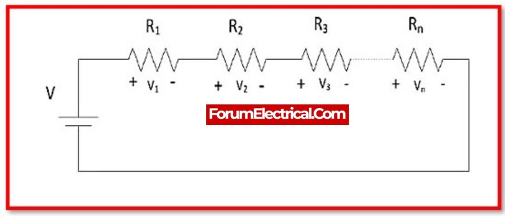
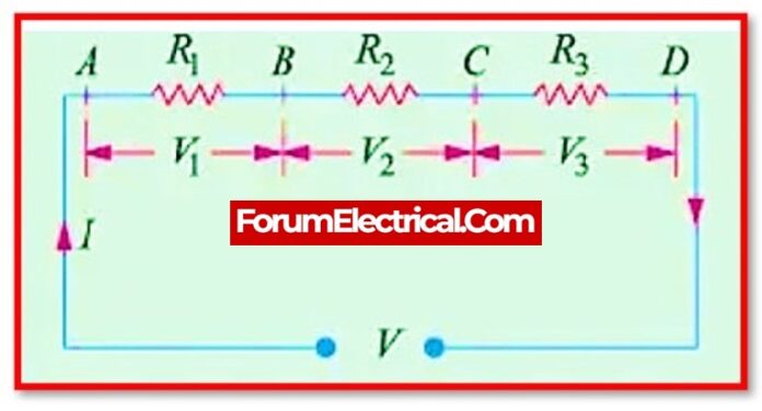
The voltage divider rule is a principle in electrical engineering that describes the behavior of a voltage divider circuit, which is a circuit that divides the voltage across a load into two or more parts. The voltage divider rule states that the voltage across each resistor in the circuit is proportional to the resistance of the resistor and the total resistance of the circuit.

Voltage Divider Rule Mathematical Expression:

The voltage divider rule can be expressed mathematically as:
V1 = (R1 / (R1 + R2 + … + Rn)) * Vtotal
where:
V1 is the voltage across resistor 1
R1 is the resistance of resistor 1
R2, R3, …, Rn are the resistances of any additional resistors in the circuit
Vtotal is the total voltage across the circuit.
The voltage divider rule is a useful tool for analyzing and designing circuits that involve voltage division. It allows engineers to calculate the voltage across each resistor in the circuit, which can be useful in predicting the behavior of the circuit and in designing it to meet specific performance requirements.
The voltage divider rule is only applicable to DC circuits. It is not applicable to AC circuits, which behave differently due to the changing nature of the current. The voltage divider rule is also only applicable to linear circuits, which obey Ohm’s Law. Nonlinear circuits, such as those containing diodes or transistors, do not obey Ohm’s Law and cannot be analyzed using the voltage divider rule.
When should the Voltage Divider Rule be utilised?
The voltage divider rule is used to simplify the solution of circuits. This rule can be used to comprehensively solve simple circuits. The basic principle behind this voltage divider rule is that “the voltage is divided between two resistors that are linked in series in direct proportion to their resistance. The voltage divider has two crucial components: the circuit and the equation.
Voltage Divider Rule Applications:
- The voltage divider is only used in circuits where the voltage is regulated by dropping a specific value. It is primarily employed in systems where energy efficiency is not necessarily taken seriously.
- The voltage divider is most typically employed in potentiometers in our daily lives. The volume tuning knob on modern music systems and radio transistors, for example, are excellent examples of potentiometers. The potentiometer’s basic design has three pins, as seen above. Two pins are attached to the potentiometer’s internal resistor, and the remaining pin is connected to a wiping contact that slides on the resistance. When the knob on the potentiometer is turned, the voltage appears across the stable contacts and the wiping contact according to the voltage divider rule.
- Voltage dividers are used to modify the level of a signal, as well as to measure voltage and bias active components in amplifiers. Voltage dividers are included in a multimeter and a Wheatstone bridge.
- Voltage dividers can be used to measure the sensor’s resistance. The sensor is linked in series with a known resistance to produce a voltage divider, and a known voltage is delivered across the divider. The microcontroller’s analogue to digital converter is linked to the divider’s centre tap, allowing the tap voltage to be measured. The observed voltage sensor resistance can be estimated using the known resistance.
- Voltage dividers are employed in sensor and voltage measurement, logic level shifting, and signal level control.


