
What is an Over Voltage Relay?
Over voltage relays are electrical protection devices that are used to prevent system voltage from exceeding a predetermined value and duration.
- What is an Over Voltage Relay?
- What is an Undervoltage Relay?
- Purpose
- Required Equipment
- Precautions
- Scope
- Testing Procedure
- Step-1: Preparation
- Step-2: Visual Inspection
- Step-3: Overvoltage Relay Test
- Step-4: Undervoltage Relay Test
- Step-5: Reset Verification
- Step-6: Functional Simulation Test
- Step-7: Documentation & Signoff
- Conclusion
When the voltage and time values cross, a tripping signal is sent to circuit breaker tripping coils. It is utilized in transformer outgoing isolation panels, LT panels, and feeder panels to control overvoltage.
Overvoltage relays continue to monitor the system’s default voltage level. If voltage level exceeds the pre-set voltage limit, the system will trigger.
What is an Undervoltage Relay?
An under voltage relay has contacts that trigger when the voltage drops below a predetermined level.
These are used to detect short circuits, prevent voltage drops & so on. These are frequently used in alternators, motors & busbars.
Overvoltage (OV) & undervoltage (UV) relays are essential safety features in electrical systems. They protect equipment such as
- Motors,
- Transformers,
- Switchgear &
- Control Circuits
against abnormal voltage levels. If the system voltage exceeds a safe level (overvoltage) or falls below the minimum operational limit (undervoltage), these relays will generate an alert or trip the circuit breaker to prevent harm.
Regular testing of these relays is an essential component of preventative maintenance, commissioning & periodic inspection programs.
This makes sure the devices work at the appropriate voltage levels, trip within the defined time frame and reset as predicted.
This post will cover a detailed, step-by-step testing technique for overvoltage & undervoltage relays, as well as important precautions & documentation requirements.

Purpose
The primary objectives of evaluating OV and UV relays are to ensure accuracy by verifying that the trip voltage meets the selected threshold and confirm operational timing that the relay functions within the indicated delay.
Required Equipment
- Secondary Injection test kit (or) Relay test kit
- Multimeter
- Manufacturer manual (with set points and tolerances)
Precautions
Follow the guidelines for handling electronic components that are sensitive to electrostatic discharge.
When testing at voltages more than 50V, special safety precautions must be taken in all places that are not clearly designated as the electrical operating areas.
- Before testing, wear PPE.
- Stay away from the tested device.
- Safety tape isolates the area.
- Proper grounding implementation.
Scope
Test cable connections and ensure proper mounting position.
Testing Procedure
Step-1: Preparation
Before starting the testing procedure, it is necessary to set up the work area and make sure all safety precautions are in place.
To avoid unintentional energization, the relay should be completely isolated from the live circuits.
Appropriate “Testing in Progress” signage should be posted to alert staff in the area.
Check the relay’s settings in the manufacturer’s manual to ensure the correct trip points & tolerances.
Also, make sure to ensure the relay test kit (or) secondary injection set is appropriately calibrated for the accurate measurements.
This preparation process reduces hazards & assures accurate test findings.
> Isolate the relay from the electrical power supply.
> Display safety signs.
> Check the relay set values against the manufacturer’s documentation.
> Calibrate the test equipment.
IEC 60255-127 covers overvoltage and undervoltage relay protection features, measurement accuracy, time-delay behavior, set/reset thresholds, operating/reset time definitions & dynamic performance.
Step-2: Visual Inspection
Before applying any of test voltages, conduct a thorough physical check of the relay & its accompanying wire.
This step assists in identifying noticeable faults that may affect performance. Inspect all wire connections to ensure that they are tight and properly terminated.
Look for
> Overheating,
> Corrosion and
> Physical damage to relay body & their terminals.
In addition, ensure that all labeling, terminal markings & nameplates are intact and legible, as incorrect markings might result in wiring or operating problems.
Checklist:
> Tightness and accuracy of wiring terminations.
> The absence of burn scars, corrosion (or) fissures.
> Clear and undamaged labels/markings.
Step-3: Overvoltage Relay Test
The overvoltage test is intended to determine the relay’s accuracy if the system voltage surpasses the setpoint.
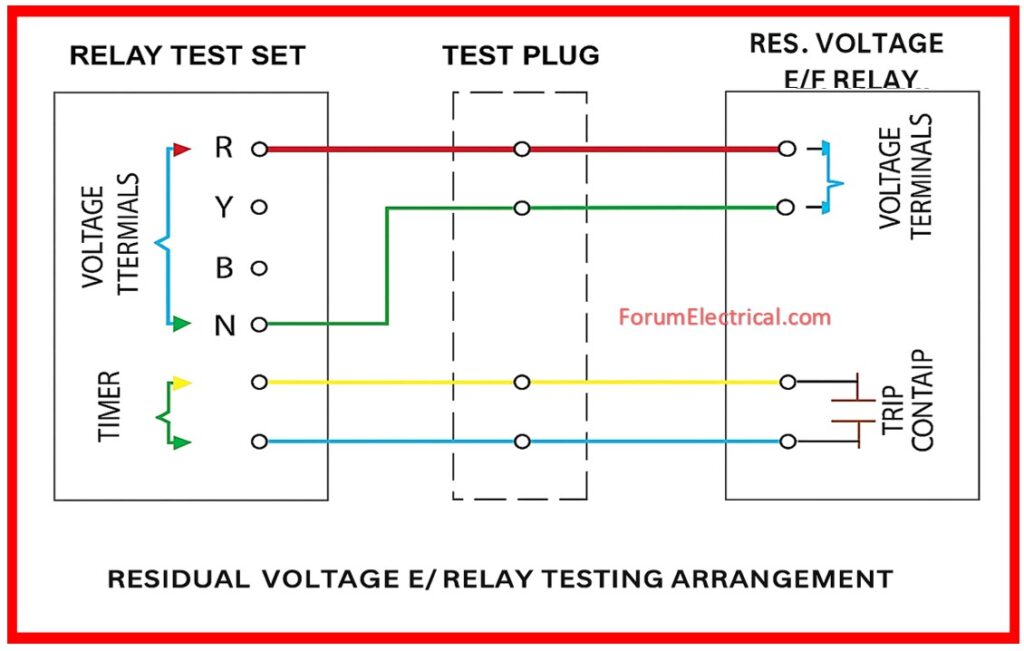
Connect the relay utilizing the relay test kit and the wiring diagram provided by the manufacturer.
Gradually increase the applied voltage over the nominal rated value till the relay operates.
Measure the trip voltage & compare it to the programmed value to ensure it is within the allowable tolerance (usually ±2%).
Measure the operation time to confirm it is consistent with the relay’s requirements.
> Increase the voltage gradually to avoid rapid relay damage.
> Keep a record of both the trip voltage and the operation time.
> Compare results to the manufacturer’s tolerances.

Step-4: Undervoltage Relay Test
This test confirms the relay’s functionality if the system voltage drops below the specified threshold.
Start by applying the nominal voltage & gradually decreasing it until the relay trips.
Note the trip voltage & compare it to setpoint to ensure compliance.
Similar to overvoltage test, check the trip time to confirm it is within the manufacturer’s restrictions.
Key Steps:
> Start at nominal voltage and progressively decrease.
> Keep a record of the trip voltage and time.
> Compare the findings to the stated limitations.

Step-5: Reset Verification
Once the trip condition has been removed, the relay must reset either automatically (or) manually, depending on its configuration.
Restore the voltage to normal condition & observe (view) if the relay resets.
Take note of the reset voltage point & make sure it follows the manufacturer’s standards.
This step validates that the relay can return to its regular functioning state after a fault has been cleared.
Checkpoints:
> Automatic (or) manual reset function.
> Reset the voltage point accuracy.
IEC 60204-1 covers over-/undervoltage protection, control circuit regulations and marking for low-voltage electrical machinery.
Step-6: Functional Simulation Test
In this step, practical applications fault conditions are generated to ensure general functionality.
Use the test kit to simulate both overvoltage & undervoltage conditions.
Ensure that the relay is active and that it is sending trip signal to proper circuit breaker or that it is activating the alarm system.
This functional verification confirms that the protection mechanism is fully operational & effective under real-world settings.
Simulation Focus:
> Overvoltage fault simulation,
> Undervoltage fault simulation and
> Proper breaker/alarm activation
Step-7: Documentation & Signoff
The maintenance logs and any future references require accurate documentation in order to function properly.
All test findings, including trip and reset points, operation times & any deviations, must be documented.
Conclusion
Overvoltage & undervoltage relay testing is essential for electrical system safety and dependability.
Relays that work properly avoid voltage fluctuations from causing costly equipment breakdowns and downtime.
For high operational standards and industry compliance, follow the above systematic testing procedure.
To protect systems over time, facilities should test often as part of preventative maintenance.
