
- Center-Tapped Transformer
- Working Principle of a Center Tapped Transformer
- Construction of Center Tapped Transformer
- Working of a Center Tapped Transformer
- Center Tapped Transformer Formula
- Difference between a Normal & a Center Tapped Transformer
- Normal Transformer vs Center Tapped Transformer
- 12-0-12 Center Tapped Transformer
- 12-0-12 Center-Tapped Transformer Specifications
- Other Center Tapped Transformers
- Where to Use Center Tapped Transformers?
- What is the difference between a Center-Tapped Transformer and a Transformer?
- Advantages of Center Tapped Transformer
- Disadvantages of Center Tapped Transformer
- Applications for Center Tapped Transformers (Centre Tapped Transformers)
- What is Full Bridge Rectifier with Center-Tapped Transformer?
Center-Tapped Transformer
A center-tapped transformer has a tapped secondary winding with a central connection. In simpler terms, the secondary winding is divided into two equal halves, with a terminal coming out of the center point. The middle tap is usually grounded to create a neutral point.
Working Principle of a Center Tapped Transformer
A center-tapped transformer functions similarly to a standard transformer. The only difference is that its secondary winding is separated into two distinct parts, allowing for the obtaining of two separate voltages across the two-line ends.
The internal process is the same: when an alternating current is applied to the transformer’s primary winding, it generates a magnetic flux in the core, and when the secondary winding is brought close, an alternating magnetic flux is induced in the secondary winding as the flux flows via the ferromagnetic iron core and changes direction with each cycle of the alternating current.
In this method, an alternating current move through the two sides of the transformer’s secondary winding and into the external circuit.
Construction of Center Tapped Transformer
As with a typical transformer, the center tapped transformer (centre tapped transformer) has primary & secondary windings.
A normal transformer has a single secondary winding, but a center tapped transformer has two equal sections. As a result, the secondary winding of a center-tapped transformer provides two equal voltages.
A tap is cut from the middle of the secondary winding to generate a centre tapped transformer. The center point has a connection to a common ground, providing a reference point for both secondary windings.
The center point is exactly at the center of the secondary winding, dividing it into two equal sections. Both segments of the secondary winding have the same number of turns.
Because it carries more voltage and current, the primary winding uses thicker wire than the secondary windings. Conversely, secondary windings use thinner gauge wires to manage lesser voltage and current.
The iron core of the center-tapped transformer (centre tapped transformer) is comprised of steel sheets that have been laminated. The transformer’s core contains both the primary & secondary windings. Laminated sheets reduce eddy current losses & improve transformer efficiency.
Working of a Center Tapped Transformer
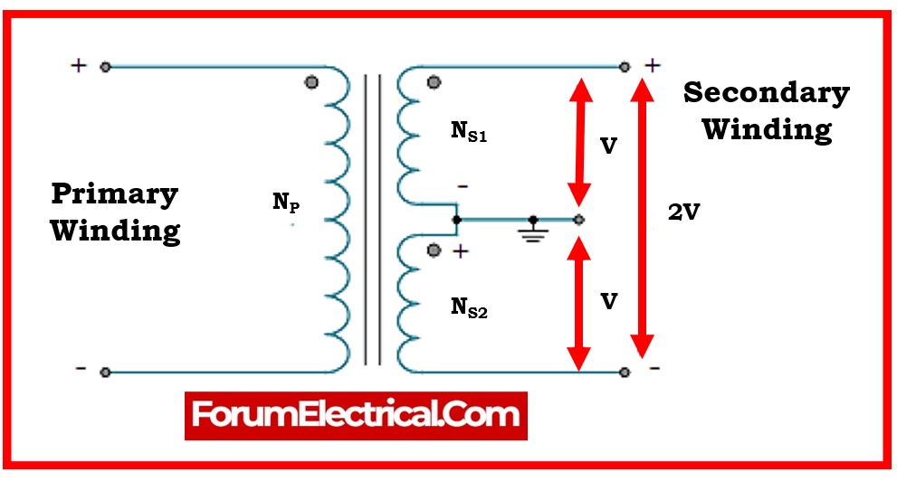
The winding arrangement & core of the transformer are shown in the image above.
When we connect the AC supply to the primary winding of the center tapped transformer (Centre Tapped Transformer), we create a changing magnetic field around it.
The magnetic field induces magnetic flux in the core, which flows through it and connects to the secondary winding. The voltage is induced in secondary winding according to Faraday’s law of electromagnetic induction.
The voltages between line 1 & neutral, & between neutral & line 2, are denoted as VS1 and VS2, respectively.
The voltage induced in one portion of the secondary coil is:
ES1=-NS1(dФ/dt)
The voltage induced in second portion of the secondary coil is:
ES2=-NS2(dФ/dt)
The secondary winding in the center-tapped transformer (centre tapped transformer) has an equal number of turns in both sections.
NS1 = NS2
Therefore,
ES1 = ES2
The voltage induced in both portions of the secondary is as follows:
ES1=-NS1(dФ/dt)
Ep=-Np(dФ/dt)
ES1= (NS1 Ep) / Np & ES2= (NS2 Ep) / Np
Similarly,
VS1= (NS1 Vp) / Np & VS2= (NS2 Vp) / Np
Therefore,
VS1= VS2 & NS1 = NS2
Center Tapped Transformer Formula
The mathematical expression between these two voltages demonstrates that they are dependent on both the primary voltage and the transformer’s turn ratio.
VS1= (NS1/Np) x Vp
VS2= (NS2/ Np) x Vp
It is important to keep remember that the outputs VS1 and VS2, respectively, are 180 degrees out of phase with one another because they have the same magnitude but opposite directions.
To do this, we also combine a center-tapped transformer with a full wave rectifier to bring both voltages into phase.
Difference between a Normal & a Center Tapped Transformer
Normal Transformer vs Center Tapped Transformer
| Normal Transformer | Center Tapped Transformer |
| A typical transformer’s secondary winding is continuous and lacks a center tap.The output voltage is provided by a single, continuous winding. | In a center-tapped transformer, the secondary winding is split into two equal parts, and the middle is where the tap is removed.Multiple output voltages are supported and a midpoint reference is created via this center tap. |
| Normal transformers generate a single-phase output voltage. | A single-phase center-tapped transformer generates two equal and opposite voltages at the center tap, resulting in a split-phase output.In a three-phase center-tapped transformer, it serves as the system’s neutral point. |
| A normal transformer generates a single output voltage from its secondary winding. | A center-tapped transformer generates two output voltages from the ends of the secondary winding & the center tap. |
| Normal transformers do not have a center tap and so do not require grounding at the center. | Center-Tapped Transformers are often grounded to ensure safety and optimum operation. |
| Normal transformers are commonly used in single & three-phase power distribution systems. | Center-tapped transformers are commonly used in power systems that require a neutral point and can accommodate both single-phase & three-phase loads. |
| Normal transformers are commonly utilized for applications requiring a single-phase output. | Center-tapped transformers are used in power distribution networks to provide a split-phase output or neutral point for both single-phase & three-phase loads. |
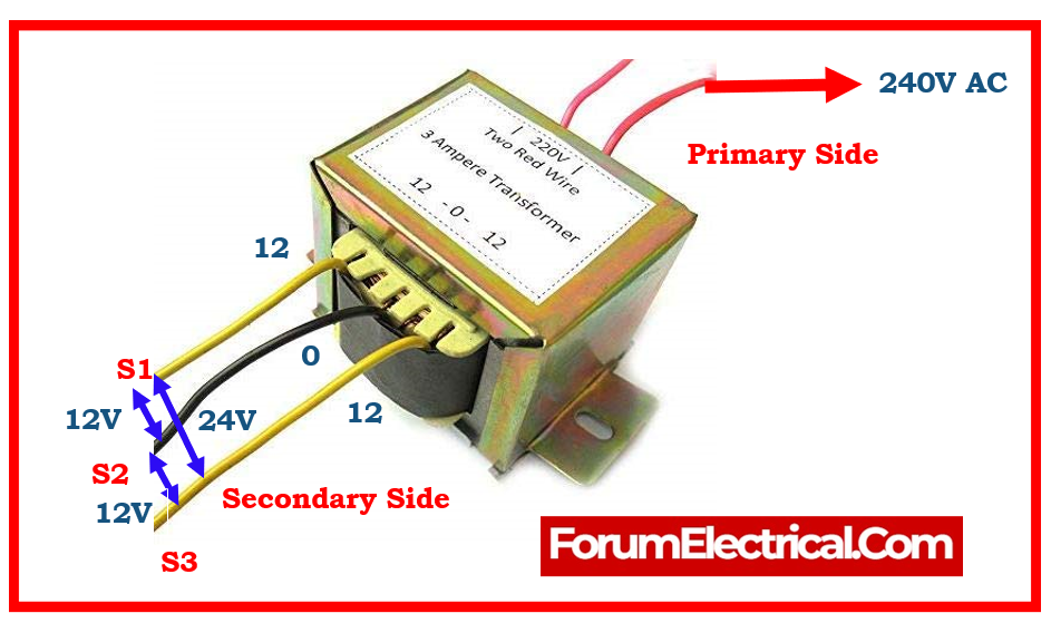
12-0-12 Center Tapped Transformer
A “12-0-12” center-tapped transformer has a center tap on the secondary winding. The “12-0-12” designation specifies the transformer’s voltage arrangement. Here’s what each component of the notation represents:
| S.No | Notation | Details |
| 1 | First “12” | The voltage between the center tap and one end of the secondary winding is indicated by the first “12”. Here, the voltage is 12 volts. |
| 2 | “0” (Center Tap) | “0” (Center Tap) is the secondary winding’s center tap. Since it is usually grounded, the voltage at the center tap serves as a reference point. |
| 3 | Second “12” | The voltage between the other end of the secondary winding & the center tap is indicated by the second “12”. The voltage is 12 volts, same as the first “12.” |
A secondary winding is included in the “12-0-12” center-tapped transformer. This winding is responsible for generating two voltages that are opposed to one another and are equal to one another.
The voltage between both halves of the winding is 12 volts, & the middle tap serves as a reference point. The total voltage across the secondary winding (from one end to the other) equals the sum of the voltages on either half, which in this case is 24 volts.
UL 5085-1 specifies low-voltage transformer specifications, including center-tapped transformers.
12-0-12 Center-Tapped Transformer Specifications
The following are the specs for a center-tapped step-down transformer.
Mounting: Vertical mount
Input Voltage: 220V AC.
Input Voltage Frequency: 50 Hz
Output Voltage: 0V, 12V, and 24V
Output Current: 1 A.
Winding: Copper.
Other Center Tapped Transformers
- 12-0-12 (2A,3A,5A) Center Tapped Transformer,
- 6-0-6 (1A,2A,3A,5A) Center Tapped Transformer,
- 24-0-24 (1A,2A,3A,5A) Center Tapped Transformer,
- 18-0-18 (1A,2A,3A,5A) Center Tapped Transformer.
Where to Use Center Tapped Transformers?
A centre-tapped transformer, commonly known as a two-phase three-wire transformer, is typically used in rectifier circuits.
When a digital project requires AC power, a transformer is utilized to step down the voltage (in our example, to 24V or 12V) & then convert it to DC using a rectifier circuit.
A center-tapped transformer has twice the peak inverse voltage of a bridge rectifier, hence it is widely employed in full wave rectifier circuits.
What is the difference between a Center-Tapped Transformer and a Transformer?
The main difference is that a regular transformer produces a single voltage. A center-tapped transformer, on the other end, gives three voltages based on where the power is drawn.
Advantages of Center Tapped Transformer
- A simple method for obtaining a split-phase output (or) a neutral point.
- Enables the use of both single-phase & three-phase loads in the common system.
Disadvantages of Center Tapped Transformer
- May cause some imbalance between the two parts of the secondary winding.
- The center tap needs grounding for safety & proper operation.
Applications for Center Tapped Transformers (Centre Tapped Transformers)
- A single transformer with a center tap produces two equal voltage outputs. It provides a positive and negative supply; therefore, it is utilized in operational amplifiers & other analog circuits that require a dual power supply.
- The usage of centre tapped transformers allows for complete wave rectification of AC power to DC power. The rectifier diode is coupled to two secondary windings that convert the AC voltage into DC voltage.
- The amplifier must have a balanced output to reduce signal noise and distortion. To reduce noise, center-tapped transformers are connected to the amplifier’s output stage.
- Because centre tapped transformers generate galvanic isolation, they are utilized to separate two electrical circuits to avoid electrical interference.
What is Full Bridge Rectifier with Center-Tapped Transformer?
A center-tapped full wave rectifier employs a center-tapped transformer (full wave rectifier center tapped transformer) as its input & the transformer contains a center-tapped secondary winding, with two diodes linked to the winding’s ends & the other ends of diodes connected to the load resistor, which converts the entire AC signal to DC signal.
The main advantage of a center-tapped full wave rectifier is it allows electric current to flow throughout both the positive and negative half cycles of the input AC signal.