
- What is a Negative Phase Sequence?
- What is Positive and Negative Phase?
- Negative Phase Sequence in Electrical Equipment
- Negative Sequence Currents
- Negative Phase Sequence Formula
- Causes of Negative Sequence Components
- Effects of Negative Sequence Components
- Negative Phase Sequence Protection of Alternator
- Negative Sequence Currents in Generator
- Negative Phase Sequence Protection of Motor
- Calculator
What is a Negative Phase Sequence?
When there is an unbalance in the system, there is an unbalance in the magnitude and phase angle of the voltage and current components.
The power system will then be filled with negative sequence components.
This negative sequence component has the same magnitude as the positive sequence component but rotates in the opposite direction in the power system.
Unbalanced loads and fault conditions can both produce this. Because of the new field having a new frequency, they will generate harmful temperatures.
Unbalanced loads and unbalanced supply voltage to a motor stator might cause a negative sequence and slow down the motor as heat production increases.
What is Positive and Negative Phase?
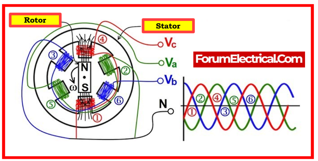
A three-phase system’s positive sequence set of currents provides a typical rotating field, a negative sequence set generates the opposite rotation, and a zero-sequence set generates an oscillating field that does not spin between phase windings.
Negative Phase Sequence in Electrical Equipment
Unbalanced currents in power system generate negative sequence currents.
The flow of the negative sequence currents in the electrical equipment (generators and motors) is undesirable because these currents generate high and potentially harmful temperatures in a relatively short time.
These high temperatures can harm the insulation of the machinery. Some of the impacts of negative sequence currents on
- Generators and
- Motors
are detailed in this post.
Negative Sequence Currents
In a three-phase system, phase current & voltage can be represented by three single-phase components.
There are three types of sequence components:
- Positive Sequence Components,
- Negative Sequence Components, and
- Zero Sequence Components.
1). Positive Sequence Components
Positive sequence components will rotate (vector rotate) in the same direction as the power system voltage & current components.
During the balanced load state, positive sequence currents exist. Only positive sequence components flow in power system if the phase currents in a generator are equal and the vectors are displaced by 120o (supplying balanced load).
When there is an unbalance in the system, there is an unbalance in the magnitude and phase angle of the voltage and current components.
2). Negative Sequence Components
Then, in the power system, negative sequence components will flow.
This negative sequence component will have the same magnitude as the positive sequence component but will rotate in the opposite direction in the power system.
3). Zero Sequence Components
When the zero sequence components flow during an unbalanced condition, current flows through the power system’s neutral.
Negative Phase Sequence Formula
The formula for calculating the negative phase sequence component of a three-phase electrical quantity is as follows:
V_ = 1/3(Va+ω2Vb+ωVc)
Where,
V_ = Negative Sequence Voltage
Va, Vb, Vc = Voltage magnitudes for phases A, B, & C
ω = ej(2П/3) = complex operator that symbolizes a phase shift of 120 degrees.
Causes of Negative Sequence Components
Numerous factors can result in the flow of unbalanced three-phase currents in alternators or generators. Among the reasons are a few of the following:
- Unbalanced loads in the system
- Unbalanced system faults
- Line to Ground Faults,
- Two Phase Faults,
- Three Line to Ground Faults,
- Double Line to Ground Faults.
- Open phases (or) faults in open circuits
Effects of Negative Sequence Components
- The surface of the rotor,
- The slot wedges of the rotor,
- The retaining rings, and
- The filed windings of the rotor of the machines
are all affected by the double frequency currents that are induced by these negative sequence components.
The rotor temperature will rise to an extremely high level as a result of these double induced high frequency currents, which will cause damage to the machine if it is operated continually.
1). Electrical Machine – Rotor Heating
Unbalanced currents generate negative sequence components, which form a reverse rotating field (opposite to synchronous rotating field, which typically induces emf in the rotor windings) in the air gap between the machines’ stator and rotor.
The reverse rotating magnetic field rotates at synchronous rates but in the opposite direction as the machine’s rotor.
In the case of cylindrical rotating machines (generators operated via steam turbines as well as motors), this reverse rotating magnetic field induces double frequency currents into the rotor body and induces double frequency currents in the pole faces in the case of salient pole machines (generators powered by hydro turbines).

The induced currents generated by the synchronous rotating magnetic field will give a high resistance channel to the normal induced currents, resulting in rapid heating.
This heating effect, in turn, causes mechanical or insulation problems in electrical machines in seconds.
2). Induction Motor Effects
Unbalanced currents flowing into the induction motor can cause:
- Single phasing
- Phase reversal
- Unbalance supply voltage
In the case of induction motors, a 5% unbalance can result in a 25% drop in motor power, even if the induction motor continues to receive the rated current prior to unbalancing.
The induction motor’s diminished electrical power is due to heating in rotor. 3% imbalance in the supplied voltage can increase rotor heating by around 20%.
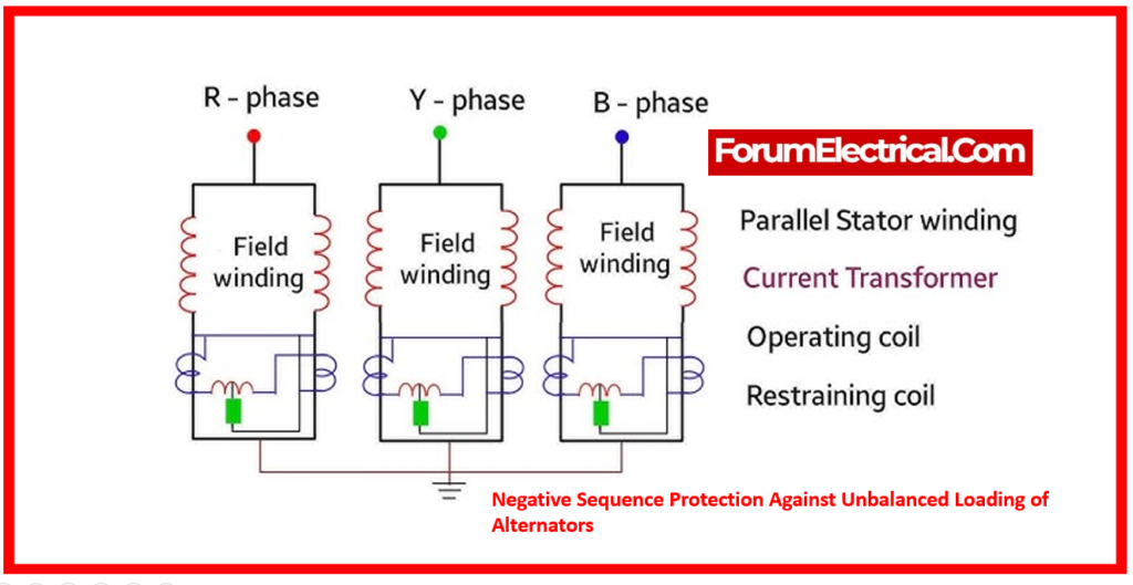
Negative Phase Sequence Protection of Alternator
Protecting alternators against negative phase sequence fault currents is essential to their safe and dependable functioning. These currents are caused by imbalanced loads or power system problems, and they can severely damage the alternator’s windings, bearings, & other components.
There are several methods used to safeguard alternators from the negative phase sequence currents:
Overcurrent Relays
These relays used to trip circuit breaker when the total current surpasses a predetermined limit. However, they can’t be sensitive enough to identify only negative sequence currents.
Negative Sequence Relays
These specialist relays detect the negative sequence component of current & trip the circuit breaker if it surpasses a safe limit. They provide more precise protection from imbalanced loads and defects.
Differential Protection Relays
This method compares the currents that enter and leave the alternator. If an error is found, it signals a malfunction in the alternator, causing the circuit breaker to trip.
Ground Fault Protection Relays
This system detects & trips the circuit breaker in the event of a ground fault, which can lead to negative sequence currents.
Selecting the Right Protection
The choice of protection strategy depends on a number of criteria, including:
Size & Type of Alternator:
Larger alternators typically require more advanced protection measures.
System Configuration:
The presence of further protective devices & the overall system grounding strategy influence the decision.
Importance of the Load:
Loads that are susceptible to disruptions may require faster and more extensive protection.
Negative Sequence Currents in Generator
Operating a generator with the unbalanced three-phase currents is one of the atypical operating conditions to that a generator may be subjected that does not necessarily indicate a failure in the generator.
This condition causes negative-phase-sequence current components to create double-frequency current in the rotor surface, retaining rings, slot wedges, and, to a lesser extent, the field winding. These rotor currents can generate extremely high and potentially deadly temperatures in a short period of time.
This may result in the operation of the generator with the unbalanced three-phase currents and the generation of negative sequence current; the effect of negative sequence current on the generator; the typical means for identifying this abnormal operating condition; and tripping/protection actions against this condition.
Unbalanced phase current flow in generator stators circulates double-frequency reverse rotation currents in the rotor body, which can harm the rotor forging, wedges, amortisseur windings, & retaining rings.
1). Generation of Negative Sequence Current
A three-phase balanced supply voltage supplied to a symmetrical three-phase winding provides a constant-magnitude flux in the airgap of machine, that revolves at synchronous speed around its circle.
Furthermore, the slots and other asymmetries inside the magnetic path of the flux generate low-magnitude space harmonics (i.e., fluxes which rotate in both directions) at many frequencies of fundamental supply frequency. During normal operation, a synchronous machine’s rotor rotates in same direction & speed as the primary (essential) flux.
When source of voltage or current is unbalanced, an additional fundamental frequency flux emerges in the machine’s airgap. However, the flux rotates in opposite direction as the rotor. This flux causes voltages and currents in rotor windings & body at double the fundamental frequency. These are known as negative-sequence currents.
The negative sequence language is derived from the vector analysis method for symmetrical components. This method represents an unbalanced three-phase system using positive, negative, & zero sequences.
The more the unbalance, the greater the negative-sequence component.
2). Post-incident conditions and recommendations for operators
ANSI-compliant cylindrical rotor generators can continuously carry 10% negative phase sequence current. This generally corresponds to an operating state in which two phases carry the rated current & the third phase receives 70% of the rated current.
Depending on the rotor design (indirectly or directly cooled), generators with two phases at the rated current and no current in the third phase can handle this unbalance for 90 to 270 seconds until rotor components are damaged. Negative-phase sequence relays are thus required to safeguard generator rotors from damage under all potential operating conditions, including phase-to-phase & phase-to-ground faults in the transmission system.
Some negative-sequence overcurrent relays deliver an alarm function with a pickup value set below the trip point. This notifies the unit operator of a negative-sequence condition preceding to a trip.
If the negative-sequence alarm is triggered, the operator should perform the following actions:
- Notify the transmission operator of the negative sequence condition & investigate any electrical issues with the transmission system.
- When a negative phase sequence alarm is triggered, operators should verify the phase currents for balance.
- Unbalance can also be caused by open conductors, disconnects, or breaker poles on-site, in addition to off-site factors.
- If there are no irregularities, alert the dispatcher to reduce the generator load until the alarm is cleared.
- Disable automatic control of the generator and reduce load until the alarm is cleared.
- If the alarm coincides with electrical switching in switchyard (or) within the plant, open the device. If the alarm clears, inspect the apparatus for appropriate operation.
Electrical engineers and technicians should:
- Check calibration of negative-phase sequence relay.
- Examine data acquisition monitoring devices (e.g., protective relay digital storage and DCS trends) to ensure the unit operated with considerable current unbalance.
- Following a negative phase sequence fault trip, the unit may not be put back into operation until an inquiry is conducted. It could have been triggered by an electrical system problem that did not resolve quickly due to faulty circuit breakers (or) protective relays.
3). Conditions for generating Negative Sequence Current in Generator
Several aberrant operating conditions cause significant currents to flow in the forged rotor, teeth, rotor wedges, end-rings, & field-windings of synchronous machines. These conditions include the following:
- Unbalanced armature current causes negative-sequence currents.
- Inadvertently energizing a machine at rest,
- Asynchronous motoring (or) generation (with loss of field)
- System asymmetries, including un-transposed lines.
- Imbalanced loads,
- Unbalanced system faults with open phases.
These system conditions cause negative-phase-sequence current components to induce a double-frequency current in the rotor’s surface, retaining rings, slot wedges, and, to a lesser extent, the field winding. These rotor currents can generate extremely high and potentially deadly temperatures in a short period of time.
A generator must be able to endure the effects of continuous current unbalance corresponding to a negative-sequence current without being damaged, as long as the rated kVA is not exceeded and the maximum current does not exceed 105% of the rated current in any phase.
ANSI C50.12-1982 & ANSI C50.13-1989 specify a generator’s ability to handle imbalanced currents in the form of negative-sequence current.
4). Negative Sequence Current’s Effect on Generator Components
A reaction field that rotates synchronously with rotor field system is generated by a three-phase balanced load and is nearly constant.
Positive, negative, & zero sequence components can be used to analyze any unbalanced state.
The positive component functions similarly to the load that is balanced.
The zero components do not generate any primary armature reaction.
The rotor is cut at twice the rotational velocity, though, because the negative component produces a reaction field that rotates in opposition to the DC field.
Due to the negative sequence in a generator crossing the air gap and appearing in the rotor (or) field as a double-frequency current, this causes double-frequency currents to be induced in the field system and rotor body.
The ensuing eddy currents are enormous and so strong that they cause overheating, which quickly softens the brass rotor slot wedges to a point where they can be extruded by centrifugal force and rise above the rotor surface, potentially hitting the stator iron.
The nonmagnetic wedges, the rotor structure’s surface, and other lower-impedance regions are where these double-frequency currents prefer to flow, generating losses and quickly destroying important rotor parts.
Serious damage may result from extreme overheating and, eventually, the wedges melting into the air gap.
Serious damage to rotor will result from improper control. Because of this, it is crucial that negative
phase sequence protection should be added to guard against the effects of imbalanced loading.
Damage to round rotor wedges and end rings is especially problematic.
5). Protections Against Negative Sequence Current and Unbalance Load
Because power systems are rarely perfectly symmetrical & loads can become unbalanced, there may occasionally be just a small percentage of negative sequence during regular operation.
Better performance is achieved by applying a positive-sequence constraint. More sensitive settings are possible with the positive-sequence constraint because it counterbalances false negative & zero sequence currents that arise from:
- Unbalanced system under conditions of high load.
- Errors in current transformer (CT) transformation.
- Transient switch-off and fault inception.
Certain contemporary relays, such as the GE G60, have an imbalance feature that protects against excessive negative-sequence current damage to the rotor.
The element features a specific time stage that is typically employed for alarm purposes and an inverse time stage that is often utilized for tripping.
Protection relays that shut down the machine in the event of excessively high negative sequence currents are placed in all large synchronous machines.
The operator should contact the machine’s manufacturer to find out the maximum permissible negative sequence values in order to correctly “set” the protective relays.
6). Tripping Modes
The negative-sequence relay trips the primary generator breaker.
This is the preferable tripping if machine auxiliaries allow it since it facilitates speedy unit resynchronization when imbalanced situations are eliminated.
The negative-sequence relay may trip machine prime mover, field, and auxiliaries if the machine auxiliaries prevent operation.
Once-through boilers, cross-compound units, and units that cannot transfer enough auxiliary loads to sustain the boiler & fuel systems may not use this strategy.
These conditions also trip turbine stop valves.
Only synchronized cross-compound units with fully interconnected stator circuits may be resynchronized with the system.
Normal starting procedures need to be utilized to return out-of-synchronized units to the line.
Establishing this method requires thorough manufacturer consultation. IEEE Std 502-1985 explains tripping.
Negative Phase Sequence Protection of Motor
- Motors that are protected by negative phase sequence protection are protected against conditions in which the phase sequence of electrical supply is reversed.
- This condition has the potential to cause the motor to overheat, which can lead to higher losses and mechanical stress.
- It does this by monitoring the sequence of voltages (or) currents, which allows it to identify this divergence in phase sequence.
- In case an abnormality is identified, the protection system will trip the motor in order to prevent any harm and ensure the operation will be safe and dependable.

 overheating & equipment failure.)