
- What is Hipot Testing?
- Importance of Hipot Test
- Why Hipot Testing is important?
- How Hipot Tests Work?
- Hipot Testing Procedure
- Cable Hipot Testing
- Cable Hipot Testing Procedure
- Formula for Hipot Testing
- What is a Hipot Test used for?
- What is a Hipot Tester?
- Safety Guidelines in Hipot Test
- Advantages of Hipot Test
- Disadvantages of Hipot Test
- Application of Hipot Test
- What is a Dielectric Tester?
- Difference between AC and DC Hipot Test
- AC Hipot Test vs DC Hipot Test
- How to do DC Hipot Testing?
- What is Very Low Frequency (VLF) Testing?
- HiPot Operator Checklist: Basic Safety Principles and Procedures
- Difference between Hipot Test and Megger Test
- Hipot Test Vs Megger Test
- Frequently Asked Questions (FAQ)
Hipot testing gets its name from the “high potential” that they generate in order to perform
- Dielectric withstand and
- Insulation resistance tests.
As a result, this testing remains a common procedure for various types of equipment.
Many hipot testers also provide exact, low-resistance, high-current outputs as well as low-resistance measurements for measuring ground bond integrity and ground resistance.
Most modern hipot testers are currently employing electronic source technologies to ensure compliance with IEC-61010, which clearly states that the voltage test equipment must be able to perform in maintaining the required voltage for a specific time period.
This post provides an overview of Hipot Testing.
What is Hipot Testing?
Hipot testing is an electrical safety test that is used to evaluate a product/component to validate the efficacy of its insulation. This can also be referred to as a dielectric-withstand test, a high potential test, or a pressure test. The dielectric strength test can assist determine whether the ground wall can withstand a higher voltage condition. This test is also useful for assessing the insulation condition of test objects such as
- Transformers,
- Relays,
- Switchgear,
- Bus-bar,
- Generators,
- Cables,
- Lightning arresters, and many more.
This test can be done on devices ranging in voltage from very low to very high.
The hipot test is extremely useful for finding terminal spacing difficulties, faulty cable junctions and terminations, crushed insulation, reduction in inside clearance and creepage, corrosive/conductive impurities, and braided shielding (or) stray wire stands.
Importance of Hipot Test
The relevance of the Hipot test is that it basically evaluates the electrical insulation range for the specific device.
This test simply determines whether or not the insulation can withstand transient overvoltages.
This might be done for a wide range of devices over a set period of time. This test is also beneficial in identifying problems with the insulation, which is typically finished with braided shielding, such as cuts, stray wire strands, tolerance mistakes, terminal spacing issues, corrosive impurities, and so on.
Many faults that occur during manufacturing, such as creepage or incorrect clearance distances, can be detected with this testing.
A Hipot test is required to measure the strain of an electronic component for security and quality assurance objectives.
Why Hipot Testing is important?
The Hipot test is significant because it determines the level of the electrical insulation of a certain device or assembly. Technicians employ testing to determine whether the insulation can withstand transient overvoltages – the ‘push’ that triggers electromotive charges to move in a wire (or) other electrical conductor.
The electrical insulation is subjected to high voltage for an extended period of time to ensure that it meets safety & quality standards.
The Hipot test identifies insulation defects by identifying the electrical insulation to the transient overvoltages.
It is essential to look for these problems. Insulation is frequently subjected to unexpected surroundings (or) circumstances that can impair device performance.
Electrical insulation to the electronic harnesses & cable assemblies can be compromised by
- Braided shielding,
- Stray wire strands,
- Tolerance mistakes,
- Corrosive pollutants, and
- Terminal spacing problems.
It can also be used to locate cuts in the insulation, as well as nicked or crushed insulation.
Hipot testing may also be carried out on manufacturing lines while the product is being manufactured.
The purpose of testing is to determine whether the assembling process of a production unit is identical as that of type tested units. Potential manufacturing faults such as creepage or inappropriate clearance lengths, a pinhole defect in insulation, & locating an expanded solder footprint can be found.
How Hipot Tests Work?
To ensure the safety and quality of an electronic equipment, a Hipot test is required. It ensures that no breakdown or perforation occurs at high voltage & that insulation distances on transmission line as well as the air are observed. Tests can be carried out between mutually insulated components of a part or between electrified parts & electrical ground. While testing, electric current will flows between two different locations in either case.
Typically, the test is performed by connecting one end of the power supply to ground & the conductor other end being tested. Conductors can be connected to either a high voltage source (or) to ground. It ensures that your testing contact is separated from all the other contacts. Hipot testers may measure between 5k and 400k volts, based on their size.
Hipot Testing Procedure
The Hipot Testing step-by-step procedure is described in detail below.
Step 1: First, open switches/CBs to disconnect the DUT from both ends.
Step 2: A discharge rod is subsequently utilized to discharge all of the conductors.
Step 3: Set CAUTION labels (or) Barricades near the HV testing area.
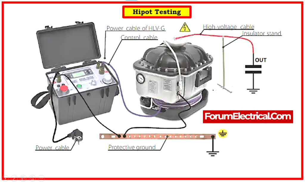
Step 4: Connect Hipot’s Master Earthing Terminal (MET) to the proper System Earthing.
Step 5: Connect the operational earthing terminal to the body earth (or) safety ground.
Step 6: Confirm that the connection is correct.
Step 7: Connect the kit’s HV terminal to the conductive portion of the test object.
Step 8: Verify all circuit phase conductors by connecting each phase to ground according to the time, current, & voltage settings that is pre-determined.
When all of these procedures have been completed, the following points must be verified.
The current flow would be measured as a result of the voltage difference between the conductors. There must be no breakdown of either the solid (or) air insulation. In addition, the current flow should not exceed the 5mA peak. In order to pass the test, the test object must be subjected to the minimum amount of stress at the predetermined voltage for 1 minute without showing signs of breakdown. Hipot testing can thus ensure the security, excellence, & consistency of essential electrical equipment.
Cable Hipot Testing
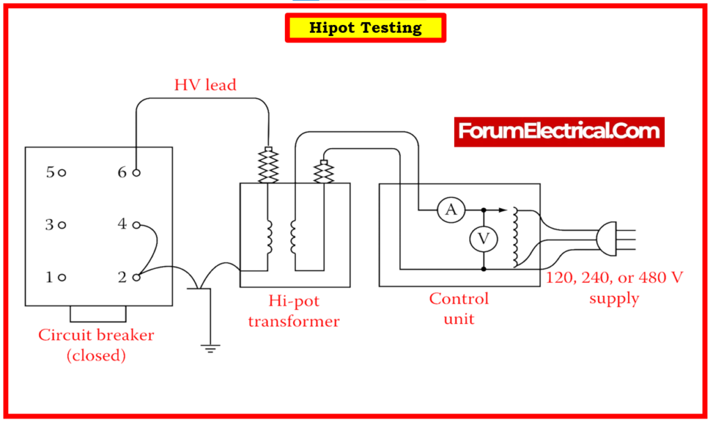
A Hipot test for the cable is used to determine whether (or) not a power cable is in good condition. This test is carried out with the help of a Hipot Test kit, which comprises
- Auto transformer,
- Test transformer,
- Some necessary components, &
- Power cord.
Cable Hipot Testing Procedure
The cable hipot testing step-by-step procedure is described in detail below.
Step 1: To get started, the power wire being checked is entirely isolated from the both ends. The cable’s 3 phases are discharged with the support of earth rods, allowing the cable to work safely.
Step 2: A control box supplies 220V AC power to the Autotransformer, and the output can be utilized to control the input voltage to the transformer’s main windings.
Step 3: The test transformer is employed here to increase the voltage to the required test range.
Step 4: If the testing type is AC Hipot testing, the test transformer’s secondary winding terminal is connected to the cable’s phase conductor.
Step 5: If the testing is DC Hipot, the silicon rectifying diode may be simply connected in series with the test transformer’s secondary winding.
Step 6: The secondary terminal of the test transformer is linked to the cable’s phase conductor via the diode, while the other terminal is routed straight to earth via the cable armor.
Step 7: Insulation between the phase conductor and the ground is evaluated. Once the power cable is in operation and charged, simply connect the cable’s armor to GND and the armor will be at ‘0’ potential.
Step 8: As a result, insulation between phase conductor and armor is tested. So, the input voltage of 220 volts is raised to the required test voltage, which ranges from 6 KV to 60 KV, and the Hipot test is done. The test voltage is increased in accordance with the voltage and insulation level of the component to be tested.
A similar procedure is followed for the remaining two phases of the power cable. We might test their physical condition of the insulation between phase and earth in this method. To assess the condition of the insulation between two phases, connect one high voltage lead to one phase and the other to another phase and ground.
In a similar way the hipot test for transformers is primarily used to determine if a resistance welding transformer is electrically stable enough to be used in production.
This type of test is quite quick and simple to execute in 5 minutes after disconnecting from the main power and the secondary power.
This test determines whether there is an internal short, which is usually caused by an insulation breakdown, or whether there is an open circuit in the secondary.
Formula for Hipot Testing
The Hipot test voltage is calculated using the formula below.
Hipot voltages are mostly used to test the insulation and ensure that there will be no electrical breakdown.
A basic thumb rule for measuring the hi-pot test voltage is twice the working voltage + 1000V.
Hipot Test Formula = 2 x (Working Voltage) + 1000 V
Ex:
If the operating voltage is 120V,
2 x 120 + 1000 = 1240V.
In general, the hipot test can be described as AC/DC. As a result, the following formula is typically used to equalize these hi-pot tests.
VDC = VAC (PEAK) = VAC(RMS) × √2
The hi-pot test period is generally 1 minute, however according to safety standards, 1 to 2 seconds are allowed for testing the manufacturing line only when the voltage increases by 20% over the 1-minute test.
What is a Hipot Test used for?
The high potential (hipot) test measures the insulation’s dielectric strength to ground. The hipot test determines the possibility that the ground wall can withstand an overvoltage event. An over-voltage is defined as a voltage greater than the device under test’s (DUT’s) highest functioning (line-to-line) voltage.
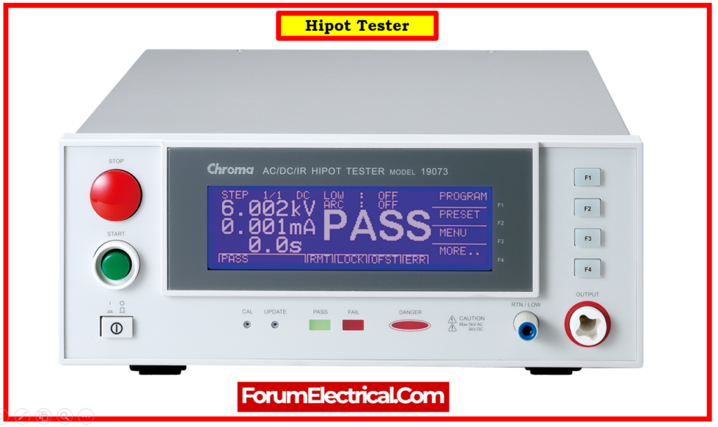
What is a Hipot Tester?
Hi-pot (high potential or high voltage) are electrical safety testing tools used to assess electrical insulation in the finished appliances, cables (or) other wiring assemblies, printed circuit boards (PCBs), electric motors, & transformers.
Safety Guidelines in Hipot Test
When working on an electrical instrument, the output is potentially dangerous voltages and currents, so it is important to check that device on a regular basis and recommend secure testing methods such as setting up a secure work area, properly training test operators, and setting up safe test procedures.
Knowing and detecting safety problems so assist a manufacturer in securing their workplace.
The primary safety considerations when doing the Hipot test are outlined below.
- Keep unauthorized workers out of the testing area.
- Arrange the test station in a safe and orderly manner.
- Make no unauthorized adjustments to the test equipment.
- Verify any custom test setups and record the appropriate ratings.
- During a Hipot test, never touch the connectors or the product.
- When there is a problem, first turn OFF the high voltage.
- Before switching connections, discharge any tested equipment correctly through DC supply.
Advantages of Hipot Test
- This test protects operators from electrical shock injuries.
- It lowers the cost of replacement or repair.
- It reduces the risk of motor vehicle injury.
- It extends the equipment’s life.
- This test assists manufacturers in determining corrosion and damaged insulation.
- This test often includes either high potential or high voltage testing.
- The key advantage of this test is its adaptability.
- This test detects material and workmanship faults, insulation weak points, conductor gap spacing, dirt, pollutants, and moisture within the insulation.
Disadvantages of Hipot Test
- It just measures total leakage current.
- Because it measures the total leakage current, a large Hipot transformer is required.
- It is not usually accepted by safety departments.
- The DC hipot test is more expensive than the AC hipot test.
Application of Hipot Test
- Ensure the insulating integrity of power transmission cables.
- The insulation between the windings and the earth is being tested.
- Checking the insulation of appliances, PCBs, & other electrical components.
- Electrical systems can benefit from preventative maintenance.
- Motors, transformers, and high-voltage systems are examples of industrial equipment.
- Manufacturing of electrical appliances
- Aerospace and defense technology
What is a Dielectric Tester?
A dielectric withstand test (or) pressure test (or) hipot test in electrical engineering is an electrical safety test done on a component or product to verify the effectiveness of its insulation. The test could be performed between mutually isolated sections of the part, (or) between powered parts and ground.
A Dielectric Strength Tester (also known as a hipot tester or dielectric strength tester or flash tester, or high voltage tester) is then used to determine this current.
Difference between AC and DC Hipot Test
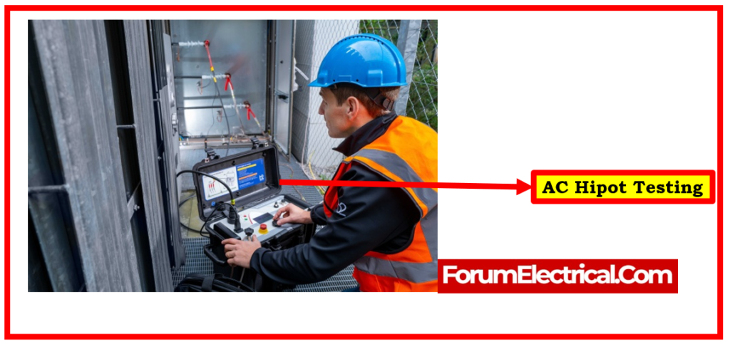
AC Hipot Test vs DC Hipot Test
| AC Hipot Test | DC Hipot Test |
| AC hipot testing is as simple as applying a higher AC voltage to the test conductor and measuring leakage current. | DC hipot is used to determine the insulation resistance of a cable by simply increasing the voltage on the test instrument. |
| AC hipot test equipment’s are huge and heavy. | DC highpot test supplies are compact and light. |
| The AC hipot test employs a lower voltage. | Higher voltage is used in the DC hipot test. |
| This test makes use of alternating current (AC) voltage. | This test makes use of direct current (DC) voltage. |
| The AC hipot test has a higher o/p current capability. | This test has a very low o/p current capability. |
| This test only measures total current and does not provide a precise assessment of leakage current. | By just reading actual current, this test provides a more exact leakage current reading. |
| This test is effective in both positive and negative voltage polarities. | Since it charges only insulation inside a single polarity, this test does not do polarity-based testing. |
| It is not economical. | It is inexpensive. |
| This cannot be used to make a diagnostic test. | When compared to other past test findings, this can be used as a diagnostic test. |
| It is not widely accepted by security agencies. | It is widely accepted by security agencies. |
How to do DC Hipot Testing?
The iTIG hipot tester (or) motor analyzer applies DC voltage to open (disconnected) windings. Depending on the test method employed, the DC voltage potential in windings is instantly increased to a predefined level or gradually increased to this level.
What is Very Low Frequency (VLF) Testing?
A direct correlation exists between the test frequency and the amount of electricity needed to activate the capacitance of a device. Power consumption during energization utilizing a VLF power source is 500 to 5,000 times lower (0.1 – 1Hz) than that of 50Hz.
Therefore, for hi-pot testing (or) offline partial discharge (PD) testing of cables, VLF testing is the more practical selection.
Given the high voltage but low power aspect of a 50Hz power supply, it is common practice to disconnect cables & voltage transformers before testing starts to compensate for their inherent capacitance. A VLF power supply will be used to test lengthy busbars or connected switchgear.
HiPot Operator Checklist: Basic Safety Principles and Procedures
- Only fully trained operators must be permitted to operate the equipment and enter the testing area.
- Make no connections to a DUT until you have confirmed that the high voltage (HV) warning light is turned OFF.
- Never come into contact with a DUT, the tester, or the test leads.
- Always attach the ground clip initially when connecting the leads to the DUT.
- Never directly touch the metal of the high voltage probe (or) HV test lead. Only contact the insulated areas while there is no high voltage present.
- Only utilize interlocked test fixtures when possible.
- Before starting a test, double-check all DUT connections. Make ensure that no other things are in the vicinity of the DUT (or) the tester.
- Maintain a clean and uncluttered environment, and prevent crossing test leads.
- To reduce capacitive coupling, suspend the test leads.
- Follow the instructions for each test accurately as printed.
- Before starting a test, double-check all setup parameters and inspect all leads for the signs of wear.
- Using a performance verification device, ensure that the tester is working properly. This will additionally confirm the test leads’ condition. Maintain a regularly scheduled calibration cycle for the equipment.
- When performing a DC test, keep a “hot stick” nearby and utilize it to discharge any connection (or) equipment that may get unplugged during the test. This is required because unexpected, harmful charges can accumulate throughout test when a connection breaks.
- When a test is over, make sure the HV light is turned off. The discharge of electricity may take some time if the test was DC.
- Ensure that the tester & test station utilize all of the hipot tester’s built-in safety features & functionalities.
- Test the memory on a regular basis to ensure uniform testing & that the setting parameters are not changed.
- Verify that the AC power supply to the tester is appropriately placed with the low impedance ground connections. Also, ensure that the emergency switch turns off all power to the tester, the DUT, and any electrical equipment & feeds in the testing area.
- In the case of a heart attack or contact with high voltage, the operator and close coworkers should be educated in compression-only CPR.
Difference between Hipot Test and Megger Test
Hipot Test Vs Megger Test
| Hipot Test | Megger Test |
| The hipot test, also known as the Dielectric Withstand Test, measures the level of electric insulation in a device by determining whether or not current can flow between two specific ends at high voltages. | An electrical test called the Megger test is used to evaluate how effectively an electrical device’s insulation is performing. |
| A high potential test is another name for a hipot test. | Alternative terminology for a megger test is a megohmmeter test. |
| By applying a high voltage to the equipment is all that is needed to conduct this type of test on electrical insulation. | By applying a small DC voltage to the equipment, this test verifies the electrical insulation. |
| In order to identify insulation failures or flaws, this test uses a higher voltage. | The insulating resistance is measured by applying a low DC voltage in this test. |
| In most condition, the voltage used for this test is far higher than the standard operating voltage. | In most condition, the voltage used for this test is far lower than the actual operating voltage. |
| The high-pot test is a way to make sure that electrical insulation is enough to withstand a typical over-voltage transient. | Insulation resistance is evaluated using this test. |
Frequently Asked Questions (FAQ)
1). What is the formula for hipot test?
The Hipot test voltage is calculated using the formula below.
Hipot Test Formula = 2 x (Working Voltage) + 1000 V
In general, the hipot test can be described as AC/DC. As a result, the following formula is typically used to equalize these hi-pot tests.
VDC = VAC (PEAK) = VAC(RMS) × √2
2). What is a hipot test for busbar?
In order to verify that there is adequate electrical isolation between conductors, HiPot (High Potential) testing is done. A HiPot test, for example, at a given voltage, the various conductive layers that make up a laminated bus bar are adequately isolated from one another.
3). What is hipot voltage?
A high voltage is directly applied to a device being tested in a hipot test, which is known as high potential test. To put more stress on the dielectric qualities of the device being tested, the test voltage is typically significantly higher than the typical operational voltage.
4). What causes hipot failure?
A breakdown in insulation causes a hipot failure. It is indicated by an abrupt rise in current flowing as an outcome of the test voltage being applied.
5). Why dielectric test is performed?
The dielectric test determines the breakdown voltage on the weak sections caused by the actions of any type of dielectric. This test is used to ensure that the component complies with electrical security testing standards as well as the insulation effectively protects users from current shock.