
- What is Centrifugal Switch?
- Components of Centrifugal Switch
- Working Principle of Centrifugal Switch
- How does a Centrifugal switch work?
- Symbol for a Centrifugal Switch
- How can a Centrifugal switch be tested?
- When the centrifugal switch fails to open, what happens?
- What happens if the centrifugal switch is not turned off after the motor is turned on?
- Why does an open motor have a centrifugal switch at the end?
- Are there centrifugal switches on all single-phase motors?
- Centrifugal switch in the Induction Motors
- Induction Motor Centrifugal switch function
- What is the most common type of split-phase motor that does not include a centrifugal switch?
- On an AC motor, what is the function of the centrifugal switch?
- Applications of Centrifugal Switch
Electrical switches known as centrifugal switches are often used in split-phase and signal phase induction motors. When a certain motor speed is compiled, this switch is employed to provide the regulated switching activity that motors required. In order to make motor building simpler, switches were formerly located within the motor frame. This design was extremely inadequate because it caused grease, dust, and oil to accumulate up on those switches. The contact operation became unreliable as a result.
What is Centrifugal Switch?
An electrical switch known as a centrifugal switch is one that receives its power from the centrifugal force that is produced by a rotating shaft. The typical source of this centrifugal force is either an internal combustion engine or an electric motor. The rotating speed of the shaft may be turned on or off by using centrifugal switches, which have been designed for this particular reason.
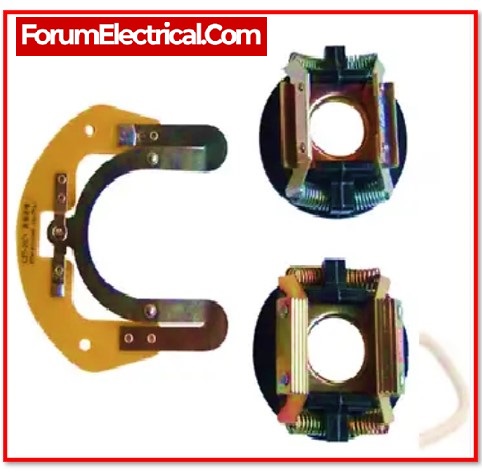
Components of Centrifugal Switch
A basic centrifugal switch is made up of two parts:
- A centrifugal mechanism is mounted on the shaft of a motor.
- A stationary fixed switch.
The centrifugal mechanism is positioned on the motor shaft so that it spins together with the shaft. It is electrically linked to the stationary switch in order to govern the start-winding circuit of the induction motor.
Working Principle of Centrifugal Switch
This switch operates on the centrifugal force concept, as the name implies. This is a made-up force that operates on rotating bodies.
When a body moves in the circular motion, a force is generated from centre of the circle that tends to push the body away from the centre, according to Newton mechanics. This is referred to as centrifugal force. It is caused by the body’s inertia. This force operates on the body, causing it to move away from the centre. This concept is also used in the washing machines.
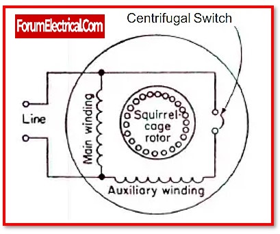
How does a Centrifugal switch work?
A centrifugal switch is an electrical switch that is often seen in
- Signal phase induction motors and
- Split-phase induction motors.
This switch is utilised to supply the engine with the regulated switching function that is necessary when the specific engine speed is generated.
The principle of centrifugal force drives the centrifugal switch. It’s not much more than an electrical switch. These switches are specifically developed for single and split phase induction motors.
The centrifugal switch is sometimes referred to as a ‘clutch’ since its action is similar to that of a centrifugal clutch used in cars.
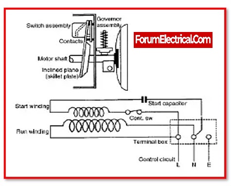
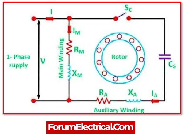
A centrifugal switch is located within the casing of a single-phase AC engine and is connected to the engine shaft. The switch is closed when the engine is turned off and still.
When the engine is turned on, the switch sends power to the capacitor and the additional coil winding in the engine, which increases the starting torque. As the engine’s revolutions per minute increase, the switch opens, indicating that the engine no longer requires a boost.
A centrifugal switch overcomes the problem with single-phase alternating current electric motors. They do not generate enough torque on their own motors to begin rotating from a complete stop.
Symbol for a Centrifugal Switch
A centrifugal switch is one of type of switch that may be represented electronically. An electronic symbol is used to represent different electrical and electronic equipment or functions in a schematic layout of an electrical or electronic circuit, such as cables, batteries, resistors, and transistors.
A switch is an electrical feature used in electrical engineering that may disconnect (or) connect with the conducting path in an electrical circuit, as well as interrupt (or) divert electrical current from one of the conductor to another.
A centrifugal switch is one that is activated by shaft rotation. It responds to speed (or) direction by opening only when the speed increases.
How can a Centrifugal switch be tested?
Before employing the centrifugal switch for applications, it is always preferable to test it. The perfect centrifugal switch should satisfy the following requirements:
- The processes need to be continuous and uniform in its whole life cycle.
- The equipment should have a limited number of components for ease of design and cheap manufacturing costs.
- There should be little areas of resistance.
- The cut-out (or) cut-in ratio should be easily adjustable without requiring major design adjustments.
- Since the switch’s communication unit is located on the outside of the motor frame, it is easily accessible. Therefore, testing, cleaning, and replacing the switch can be done without disassembling the motor assembly.
When the centrifugal switch fails to open, what happens?
If the start switch does not open when required, the start winding will oxidise, overheats and ignite, preventing the engine from starting the following time. If the centrifugal start switch is not closed, the engine’s primary winding will overheat without failing.
What happens if the centrifugal switch is not turned off after the motor is turned on?
At about 70 to 80% of the full speed of the engine, the centrifugal switch should be turned off. If it isn’t removed, a strong current will keep flowing through the engine’s starting winding, which will finally cause the starting winding & engine to break. Also, the speed and current can’t go as maximum as they could.
Why does an open motor have a centrifugal switch at the end?
An electronic switch known as a centrifugal switch operates by using the centrifugal force produced by a rotating shaft, which is often an electric motor (or) a gas engine. The switch is used to turn off the engine’s starting winding when the engine is getting close to its normal speed.
Are there centrifugal switches on all single-phase motors?
There is no centrifugal switch, so when the engine reaches the running speed, the start winding turns into an additional auxiliary winding. This makes it a two-phase motor essentially. Because there is no centrifugal start switch, they are regarded to be the most stable and reliable single-phase motors.
Centrifugal switch in the Induction Motors
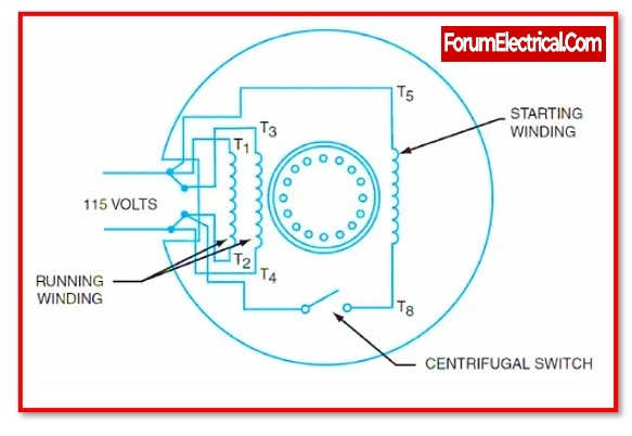
Induction motors have a single-stator winding as well as an auxiliary winding. A single-phase alternating current is applied to the stator coil. However, the single-stator winding cannot generate enough rotating field to generate starting torque. As a result, an auxiliary winding is accorded.
This auxiliary winding produces a field that is out of phase with that that is generated by the stator winding. As a consequence, the resulting field generates a starting torque & starts the motor. When the motor is started, the rotor creates a pulsating field that excludes the stator filed.
The circuit that supplies power to the auxiliary winding has to be disconnected when the speed of the motor exceeds a certain proportion of the synchronous speed. For induction motors, this is when the centrifugal switch pertains into effect. A centrifugal switch is used to open the circuit & disconnect the auxiliary winding in this condition.
Induction Motor Centrifugal switch function
The spring dish that makes up the centrifugal mechanism is attached to the motor shafts, and the calibrated weights are attached to the spring dish’s base, which is facilitated (supported) by a steel plate. This mechanism is mounted on the motor shafts. When the switch contacts are in their closed position, sufficient power is delivered to auxiliary winding so that the starting torque may be produced.
The calibrated weights are subjected to centrifugal force while the rotor rotates. When this force exceeds the spring force of the disc at a certain speed, the switch contacts open owing to centrifugal force. The weights are pushed away from the rotor shaft, cutting the auxiliary winding off from the circuit.
Three elements may be observed at the crucial operating point:
- The spring force reduced linearly.
- According to the speed of the rotor, the centrifugal force increases with greater efficiency.
- The weights’ radius is widened and increased.
What is the most common type of split-phase motor that does not include a centrifugal switch?
The capacitor-start capacitor-run split-phase motor, in general, does not include a centrifugal switch to separate the starting winding.
The cage rotor and two windings on the stator of the capacitor-start-capacitor-run motor are referred to as the primary and auxiliary windings. The two windings are rotated 90 degrees in space.
There are two capacitors in this system, one of which is utilised upon startup and is known as its starting capacitor. The other is a functional condenser, which is utilised to run the motor continually.
As a result, this engine is known as Capacitor Start Motor Run Capacitor Run. The Two Value Capacitor Motor is another name for this motor. This motor has two capacitors.
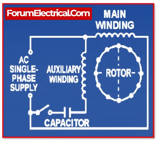
Another type of single-phase AC motor is a Permanent Split Capacitor (PSC) Motor, particularly a split-phase (splitting-phase) induction motor with a permanently attached capacitor. It does not need the use of a centrifugal switch.
It also includes a cage rotor, like a Capacitor Start & Capacitor Start Capacitor Run Motor, & two windings known as main and auxiliary windings. It just has one capacitor, which is linked in series with the starting winding.
During both the starting of the process and while it is running, the capacitor C will remain continuously connected to the circuit. Because the capacitor is still connected, no starting switch is provided for this type of motor.
On an AC motor, what is the function of the centrifugal switch?
After the motor has been started, the starting capacitor (or) double capacitor on a single-phase motor will be disconnected using the centrifugal switch.
Applications of Centrifugal Switch
This switch is also employed in systems where speed detection is critical for device safety and good operation. The centrifugal switch has the following applications:
- Overspeed protection in engines, generators, and other machines.
- Used in DC motors, conveyors, escalators, and lifts, among other things.
- These are also used to detect under-speed in devices like blowers, fans, and conveyors.
- Also used in systems where a loss of speed could result in device damage or material losses.