
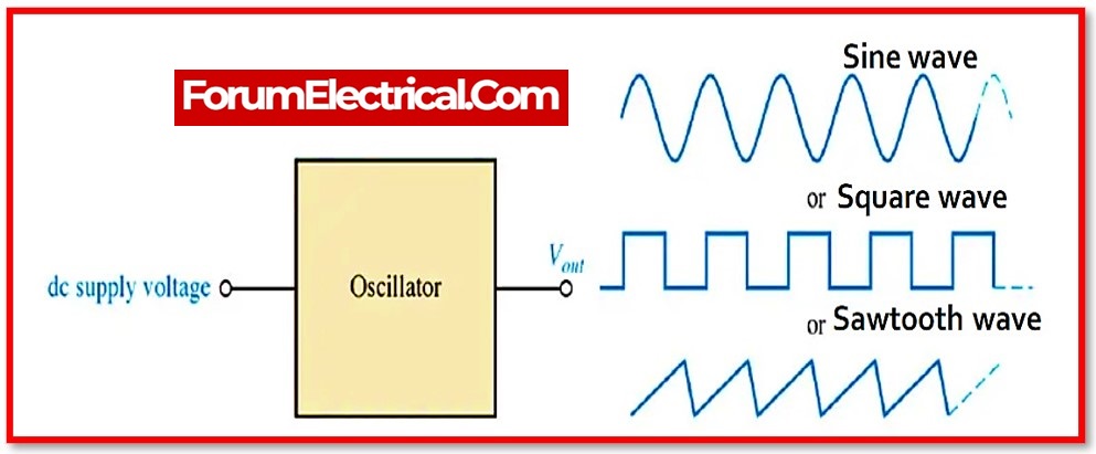
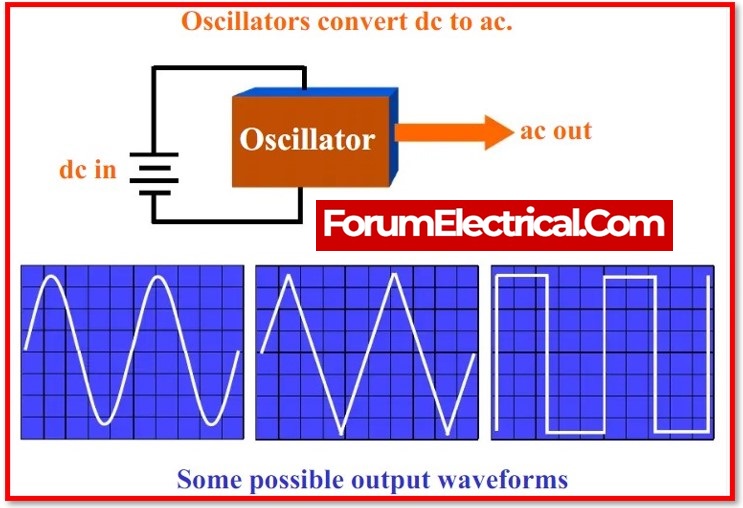
An oscillator is a device or electronic circuit that can convert a steady-state signal into an oscillating signal.
The oscillatorconverts a steady-state DC signal into a periodic AC signal of the desired frequency.
Oscillator has numerous applications in electronics engineering and is also commonly used in electrical engineering.
Basically, oscillation is not limited to electrical or electronic oscillators; mechanical oscillators are also available.
What is Oscillator?
The oscillator is a mechanical (or) electronic device whose working principle is that the periodic change between two things is determined by changes in energy.
- Radios,
- Watches,
- Metal detectors, and
- A variety of other devices
use oscillations.
The oscillator converts direct current (DC) from the power supply to alternating current (AC), which is used in many electronic devices.
A sine wave and a square wave are used in the oscillator. The best examples of oscillators are the signals broadcasted by television transmitters and radios, as well as CLKs used in computers and video games.
Principle of the Oscillator
The oscillator is a mechanical (or) electronic device that operates on the principle of oscillation. The periodic variation between the two is determined by changes in energy.
Oscillations are used in watches, radios, metal detectors, and a variety of other devices.
How Does an Oscillator Work?
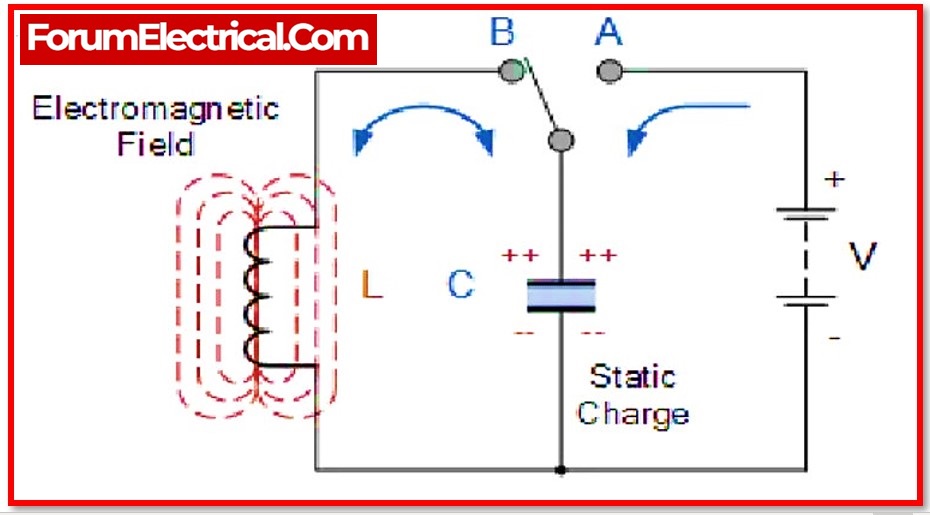
1). Simple oscillator circuit’s concept
A simple electrical circuit consisting of a capacitor and an inductor connected in parallel can illustrate the basic concepts of an oscillator.
However, understanding that circuit requires a basic understanding of inductors and capacitors.
The capacitor stores electrical energy in the form of charge, whereas the inductor stores electrical energy in the form of an electromagnetic magnetic field.
In parallel, a capacitor and an inductor are connected.
Assume the capacitor is fully charged, and the capacitor now proceeds discharging through the inductor, storing electrical energy in the form of an electromagnetic field.
There will be no current flow in the electric circuit when the capacitor is fully discharged. The capacitor is fully discharged and the inductor is fully charged in this condition.
The inductor now starts to discharge through the capacitor, and the capacitor begins to charge in the opposite polarity.
So, the charging and discharging of the capacitor capacitor and inductor produces an oscillating signal, or that the repeatable get and receive of electrical energy between the capacitor and inductor generates oscillations.
2). Amplifier-powered Oscillator Circuit
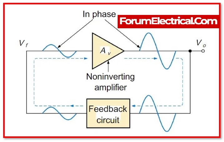
An amplifier with feedback can be used to create an oscillator circuit. The feedback could be positive or regenerative.
The feedback signal is a portion of the amplifier’s output signal that is fed back to the amplifier’s input.
An oscillator circuit with an amplifier can produce continuous constant amplitude oscillations.
When apply a sinusoidal signal as the amplifier’s input, the output will be the multiplication of the amplifier’s gain and the input signal.
The feedback circuit now receives the amplifier’s output as an input.
In general, the feedback circuit is nothing more than a frequency selective or resonant circuit that determines what fraction of the amplifier’s output signal is to be sent to the amplifier’s input as feedback signals.
When the feedback circuit’s output signal is added to the input signal while the amplifier’s input signal is removed, the feedback signal acts as the amplifier’s input.
After removing the input signal, select which type of oscillation (sustain or not) required, which is determined by multiplying the gain of the amplifier by the feedback fraction of the feedback circuit.
As a result, the oscillator circuit’s input is not required at all times during oscillator operation.
The input is only required to start the oscillation; once started, the input can be removed, or the oscillator can output without input.
Types of Oscillators
There are two kinds of oscillator circuits:
- Linear and
- Nonlinear oscillators.
The sinusoidal input is provided (given) by the linear oscillators.
In the linear equilibrium, the linear oscillators are made up of a mass m and its force.
By lowering the hook, the spring generates a force that is linear for small displacements.
The various types of oscillator circuits are listed below
- Resistor-Capacitor Oscillators (RC)
- Inductor-Capacitor Oscillators (LC)
- Armstrong Oscillator
- Crystal Oscillator
- Hartley oscillator
- RC Phase Shift Oscillator
- Colpitts Oscillators
- Cross-Coupled Oscillator
- Dynatron Oscillator
- Meissner Oscillator
- Optoelectronic Oscillator
- Phase Shift Oscillator
- Wine Bridge Oscillator
- Robinson Oscillator
- Tri-Tet Oscillator
- Tuned Collector Oscillator
1). Resistor-Capacitor Oscillators (RC)
The RC oscillator is a simple circuit that can be built on a breadboard using simple components.
An RC Oscillator is a type of feedback oscillator that is constructed with resistors and capacitors, as well as an amplifying device such as a transistor (or) operational amplifier.
The amplifying device feeds back into the RC- network, resulting in positive feedback and repeated oscillations.
Most microcontrollers and many other digital integrated circuits (ICs) that require a clock signal to perform actions include an RC oscillator network to create their internal clock source.
2). Inductor-Capacitor Oscillators (LC)
LC Oscillator which stands for “Inductor-Capacitor” Oscillator An oscillator is a specific type oscillator that makes use of a tank circuit to generate positive feedback for the purpose of keeping oscillation continuing.
An inductor and a capacitor, in addition to an amplifying component, found in the Inductor-Capacitor Oscillator.
3). Armstrong Oscillator
The Armstrong oscillator is called a “ticker oscillator” because the oscillations that are magnetically linked to the tank indicator should be caused by the different parts of the feedback signal.
But the oscillation has been continuing for a long time. The frequency f is shown in the following equation.
The Meissner oscillator and the tickler oscillator are other names for the Armstrong oscillator.
f = 1 / 2Π√LC
The Armstrong oscillation uses the transistor, to obtain the 180-degree phase shift oscillation.
The output comes from the primary transformer, which has a transistor, and the feedback comes from the secondary coil of the transformer.
The primary coil is used to switch the polarity of the secondary coil by looking at the dots. By putting together, the capacitor C1 and the primary of the transformer, can get the operating frequency.
4). Hartley Oscillator
An electronic oscillator is the Hartley oscillator. The tuned circuit determines the frequency of this oscillation.
Because the tuned circuit consists of a capacitor and an inductor, it is an LC oscillator.
The tuned circuit of the Hartley circuit consists of single capacitor in parallel with the two inductors in series.
The feedback signal is taken from the centre connection of the two inductors for oscillation purposes.
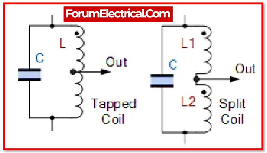
The Hartley oscillator is similar to the Colpitts oscillator except that it uses a pair of tapping coils instead of two tapped capacitors.
The above circuit generates an output voltage across inductor L1 and feedback voltages across inductor L2.
The mathematical expression for the feedback network is given below.
Feedback network = XL2 / XL1 = L2 / L1
5). Colpitts Oscillator
This oscillator is made up of inductors and capacitors. The feedback for the active devices is provided by the Colpitts Oscillator, which is made up of two capacitors connected in series across the inductor and taken from the voltage divider.
Gain devices such as the
- Bipolar junction,
- Field-effect transistor,
- Operational amplifier, and
- Vacuum tubes
are used in Colpitts circuits. The output is connected to an input in a feedback loop; it has a parallel tuned circuit and functions as a band-pass filter; and the oscillator’s frequency is used.
Because this oscillator is an electrical dual of the Hartley oscillator, the feedback signal is obtained from the inductive voltage divider, which has two coils in series.
6). Multi-Wave Oscillator
The Multi-Wave Oscillator is extremely comparable to the electronic oscillator, and it possesses the ability to both receive and transmit information that is vibratory.
The multi-wave oscillators are only used for research and experimentation on historical instruments.
The printed circuit board with the golden ratio antenna is displayed by the multi-wave oscillator unit.
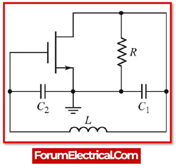
7). Clapp oscillator
In electronics, the Clapp oscillator is a kind of LC oscillator. The frequency is set by the circuit’s inductance and capacitance, which are generated from a transistor and a positive feedback network.
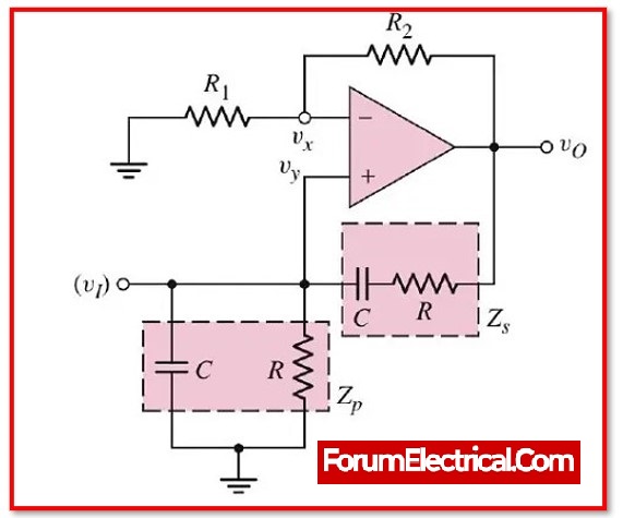
8). Wein Bridge Oscillator
Sine waves are produced by the Wien-Bridge Oscillator, which is a type of phase-shift oscillator. It resembles a bridge in that it has four limbs that are connected to one another.
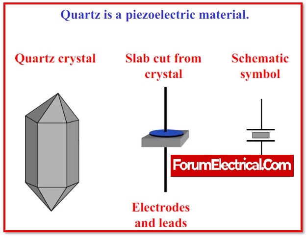
9). Crystal Oscillator
A piezoelectric crystal is used in conjunction with a piezoelectric electronic circuit to produce an electrical signal that has a very specific frequency.
This is accomplished by utilising the vibrating crystal’s mechanical resonance.
10). Tuned Collector Oscillator
A tuned collector oscillator is made up of a transformer and a capacitor that are connected in parallel and switched by a transistor.
This is the most fundamental LC oscillator schematic.
The tank circuit circuit is formed by the primary coils of the transformer and capacitor, with the secondary coil giving positive feedback, that also returns some of the energy generated by the tank circuit to the transistor’s base.
Characteristics of an Oscillatory Circuit
Oscillatory circuits are made up of LC networks, RC circuits, and quartz crystals, among other things.
The circuit will not operate in the open switch condition. However, once the switch is closed, the circuit starts to operate.
When the switch is closed, the capacitor in the circuit starts to discharge. Electrons begin to move through the circuit as a result of the discharge of the charged capacitor.
The flow of electrons generates current in the circuit, but in the opposite direction of the flow of electrons.
Flux linkage is observed as a result of the current flowing through the inductor. As a result, a magnetic field is created near the inductor.
As a result, power/energy is stored in the inductor as a magnetic field. Emf is produced by the stored energy in the inductor.
Current will begin to flow through the circuit again as a result of the generated emf.
As a result, charges will flow, and the capacitor will eventually charge and store energy in the form of an electrostatic field.
Continuous oscillations will result from the alternate charging and discharging of the capacitor and inductor.
It should be noted that the circuit produces damped oscillations.
The oscillator is supposed to provide such oscillations, but this does not always occur.
Frequency of Oscillator circuit
It is also known as the resonant frequency. Its basic definition is the frequency of oscillations. Typically, the initial frequency of the oscillator is not maintained over the entire(full) cycle of oscillations.
This is due to the fact that these resistors, inductors, and capacitors change as the temperature of the circuit rises.
As a result, there is a formula for the oscillator’s resonant frequency:
XL = 2πfL
Xc = 1/2πfC
For resonance to occur
XL = XC
2πfL = 1/2πfC
2ΠL(f) 2= 1 /2ΠC
f 2= 1 /(2π) 2LC
The expression for a tuned LC circuit’s resonant frequency
fr = 1 / 2Π√LC
Advantages of the Oscillator
- An oscillator is durable equipment. Since it does not rotate, there is a reduced risk of new damage being introduced into the system as a result.
- The frequency of the oscillation can be altered with relative ease.
- The frequency of oscillation demonstrates behaviour that is consistent.
- It has a lower decibel level.
- It is a really effective piece of equipment.
Disadvantages of the Oscillator
- The major disadvantage of oscillators is that they must be stabilised with control heaters.
- If the oscillator is not kept at a constant temperature, it will drift off frequency, and it is not a better option to transmit over a wider than necessary bandwidth.
- The frequency will be affected on either side of the off-ending transmitter.
Applications of the Oscillator
- Quartz watches which use crystal oscillator.
- Used in a variety of audio and video systems.
- Used in a variety of radio, television, and other communication devices.
- Computers, metal detectors, stun guns, inverters, ultrasonic, and radio frequency applications all make use of this material.
- Clock pulses are generated for microprocessors and micro-controllers.
- Used in buzzers and alarms.
- Metal detectors, stun guns, inverters, and ultrasonic devices all use this material.
- Used to power decorative lighting (e.g., dancing lights).