
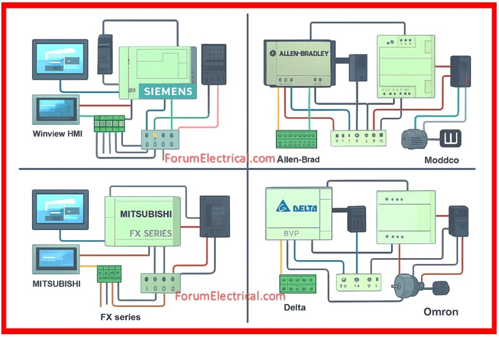
Modern companies depend on the automation systems to make sure that machine operations are accurate, efficient, and safe. One of the most trusted systems is a Siemens PLC-based automation system, which combines
- How Does Siemens PLC Control Everything?
- How does a Siemens PLC system get power and keep it Protected?
- What Input Devices feed the PLC? How are they wired?
- How Do PLC Output Devices Work?
- How Do HMI and Communication link the System?
- What Coloring Codes and Conventions for Wiring?
- How does Operation Work End-to-End?
- Summary
- Sensors,
- Actuators,
- Power supply, and
- Communication networks
into a single, cohesive control platform.
A Siemens PLC system functions as the “brain” of an automated machine (or) line. It collects sensor signals, executes logic in milliseconds, and controls actuators (motors, valves, drives). It improves efficiency, accuracy, uptime and safety by including strong I/O modules, industrial communications & an operator HMI.
Despite conventional relay logic, a PLC (Programmable Logic Controller) provides flexibility, diagnostics and scalability making it perfect for manufacturing, process control & machine automation applications.
Let us explore each component in depth using real-world inquiries and clear explanations.
How Does Siemens PLC Control Everything?
A Siemens Programmable Logic Controller (PLC) from the S7-1200 (or) S7-1500 series, which functions as the system’s primary, is the system’s heart. Using a cyclic scan method, it operates by reading inputs, then executing logic and finally writing outputs.
Consequently, the programmable logic controller (PLC) is able to continually monitor sensors, process logic in milliseconds & update actuators when necessary.
Modules such as
- Digital Inputs (DI),
- Digital Outputs (DO),
- Analog Inputs/Outputs (AI/AO) and
- Communication ports such as PROFINET (or) RS-485
are used to provide support for the personal computer rack or central processing unit (CPU).
Therefore, every terminal (for example, “8.2, 7.9, 6.4”) maps automatically to PLC addresses such as I0.0 or Q0.1, which guarantees that every sensor & actuator is addressed in the appropriate manner.
In-built reliability features include watchdog timers, which can detect program freezes, diagnostics which can identify problems with wiring (or) modules and retentive memory, which can maintain settings long after the power is turned off.
As a result, Siemens PLCs are extremely resilient and can operate around the clock.
How does a Siemens PLC system get power and keep it Protected?
For the purpose of providing power to the programmable logic controller (PLC), sensors, relays, actuators, a switching power supply unit (PSU) is responsible for converting the primary voltage (230 V (or) 400 V AC and in some of the configurations 320 V AC) into a regulated 24 V DC.
There is a simple color convention:
- Red represents +24 VDC and
- Black represents 0 V/GND.
Best practices comprise the following in order to guarantee a safe and uninterrupted operation:
In order to guard against overcurrent, using MCBs (or) fuses upstream is recommended.
Lightning or voltage spikes can be protected against by installing surge protection devices (SPD).
In order to distribute loads over specific circuits, 24 V DC breakers and fuses are utilized.
When it comes to safety compliance, maintaining a strong protecting earth (PE) is essential.
The scope of the power supply is quite important; in order to manage peak demands, engineers often add twenty to thirty percent more headroom.
In plants that are considered to be mission-critical, a DC UPS (or) buffer module is utilized to ensure that even brief power outages do not stop the PLC.

What Input Devices feed the PLC? How are they wired?
Input devices are the “eyes & ears” of the programmable logic controller (PLC) providing real-time status of machine.
These include the following:
There are proximity sensors (inductive/capacitive, PNP/NPN types) that can detect components without making physical contact with them.
It is possible to detect end-positions using limit switches.
Sensors and transducers that measure pressure, whether it be hydraulic (or) pneumatic.
In order to extend the I/O capacity, RS-485 extension modules with 8-in/8-out ports.
Each sensor needs to have three connections: a signal wire that goes to a PLC digital input, a +24 V connection, and a 0 V connection.
It is common practice to utilize shielded cables for analog & communication lines, with the shields being grounded at only one end, in order to limit the amount of electrical noise.
Ex: Limit_SW_Head → I0.1
How Do PLC Output Devices Work?
The outputs of the automation system are the “muscles” of the system, and the PLC is responsible for directing them through digital (or) analog signals:
Solenoid valves are used to control the flow of air (or) hydraulic fluid. They are operated using digital outputs.
Useful for accurate motion, AC servo motors and drives can communicate with the programmable logic controller (PLC) through pulse/dir (or) PROFINET.
In order to perform tasks such as indexing, stepper motors and drives are able to provide incremental stepwise movements.
Controlled by analog signals (0–10 V, 4–20 mA) via fieldbus communication, induction motors and variable frequency drives (VFDs) make it possible to operate at various speeds.
Interposing relays (or) contactors are utilized in order to accommodate some actuators that require a larger current than what a PLC DO is able to carry out.
Additionally, in order to decrease voltage spikes, engineers protect circuits by using flyback diodes (for DC coils) (or) RC snubbers (for AC coils).
How Do HMI and Communication link the System?
The absence of the operator communication is a fundamental component of the every modern and advanced automation system.
In this configuration, a Winview HMI (Human Machine Interface) (or) Siemens HMI functions as a touchscreen panel that allows operators to start and stop equipment, alter parameters and monitor alarms.
When it comes to communication, PROFINET (or) RS-485 serial connections are typically utilized.
RS-485 modules can also link external devices such as variable frequency drives (VFDs) (or) remote input/output blocks, which enables distributed automation.
Having bus termination, the appropriate baud rate, and a node ID that is unique to each device are all components of a proper configuration.
The human machine interface (HMI) makes the display of real-time warnings, diagnostic messages, production trends & methods an additional source of value.
Because of this, operators are able to immediately spot problems and take corrective action, which results in a reduction in downtime.
What Coloring Codes and Conventions for Wiring?
Improving both safety and maintenance can be accomplished by adhering to a correct wiring color convention:
- Black = 0 V DC (common)
- Red = +24 V DC
- Blue/Yellow/Green = signal wires (depending on the location, according to IEC/EN 60204-1)
Additionally, the terminal block & the PLC input/output tag should be matched with the numbers and labels that are attached to both ends of each wire.
Engineers are also responsible for maintaining as-built wiring drawings that are continually updated for long-term reference after the commissioning process.
How does Operation Work End-to-End?
Each step of the process is carried out as follows:
PLCs receive signals from sensors that identify machine conditions such as the presence of an object, the pressure being OK, and the end-stop being reached.
While the logic of the PLC is being executed,
- Interlocks,
- Timers,
- Counters & safety conditions are being evaluated.
The PLC is responsible for energizing outputs, which may include activating solenoid valves, driving motors (or) directing a Variable Frequency Drive (VFD) speed reference.
In addition to displaying live data and alerts, the human machine interface (HMI) also provides the ability to acknowledge warnings and make adjustments to parameters.
A data interchange can take place between drives, remote modules (or) supervisory SCADA/DCS systems through the use of RS-485/PROFINET connectivity.
Repetition of this closed loop cycle occurs at regular intervals of a few milliseconds, which guarantees deterministic control of the industrial machinery in real time.
Summary
Automation systems that are based on Siemens PLCs integrate many components, such as
- Sensors,
- Actuators,
- Power supply,
- Communication modules and
- Human Machine Interfaces (HMIs)
into a unified environment that enhances industrial efficiency.
By way of its modularity, structured wiring, and comprehensive diagnostics, it guarantees the highest possible uptime and safety.
When it comes to the future of automation, Siemens PLC systems are designed to provide dependability and scalability, regardless of whether they are controlling a single machine (or) a complete production line that is being controlled.