
The selection of step size and the number of capacitor steps is one of the most important aspects in the design of Automatic Power Factor Correction (APFC) panels.
- APFC Panel Step Size Selection
- Stage-1: Maximum Step Size Selection
- Stage-2: Minimum Step Size Selection
- Stage-3: Number of Steps in APFC Panels
- Stage-4: Design Objectives
- Stage-5: Step Configuration Examples
- Stage-6: Step Combination Strategy
- General Recommendations Table
- APFC Panel Step Size Selection Table
- Important Design Guidelines
- Conclusion
Proper selection directly impacts
- Power factor correction accuracy,
- System stability,
- Equipment life and
- Overall panel cost.
An optimized design ensures an efficient reactive power compensation while minimizing switching stress & investment cost.
APFC Panel Step Size Selection
Stage-1: Maximum Step Size Selection
The maximum capacitor step size depends on
- Load variation,
- Current transients and
- Voltage transients.
Large load variations need larger capacitor steps.
Switching large capacitors (>100 kVAr) produces high inrush current up to 75 kA.
Large switching may cause voltage transients affecting sensitive equipment.
Recommendation
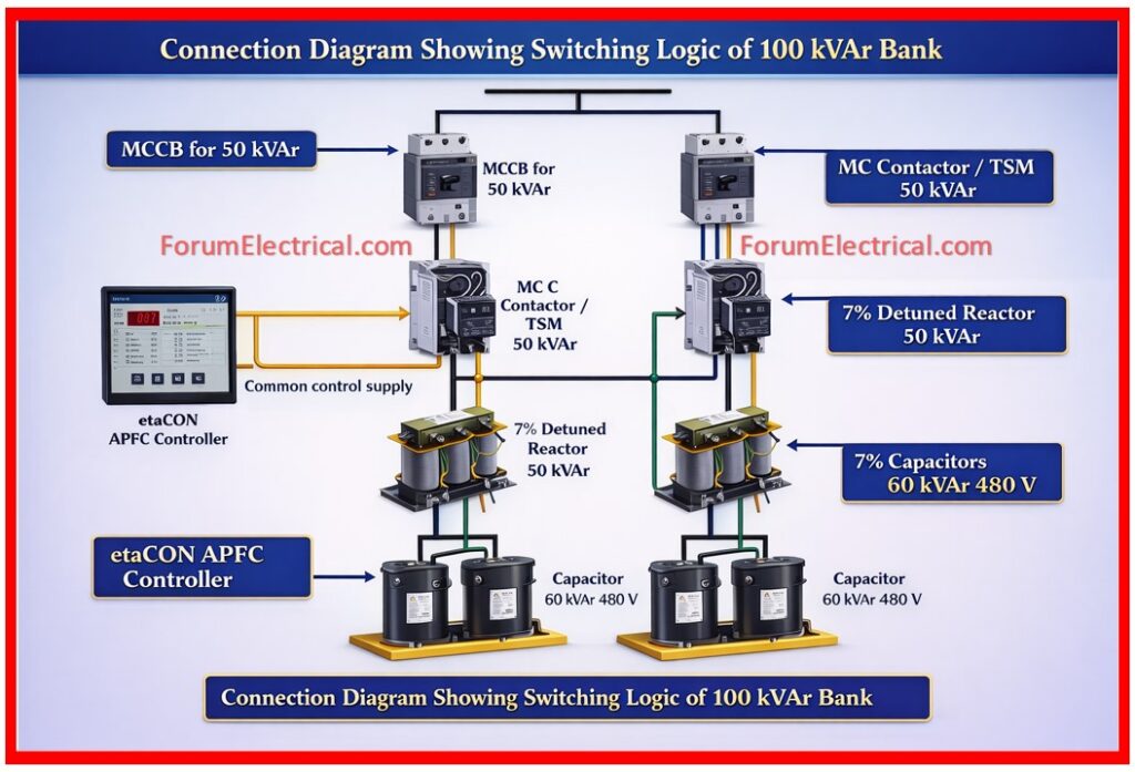
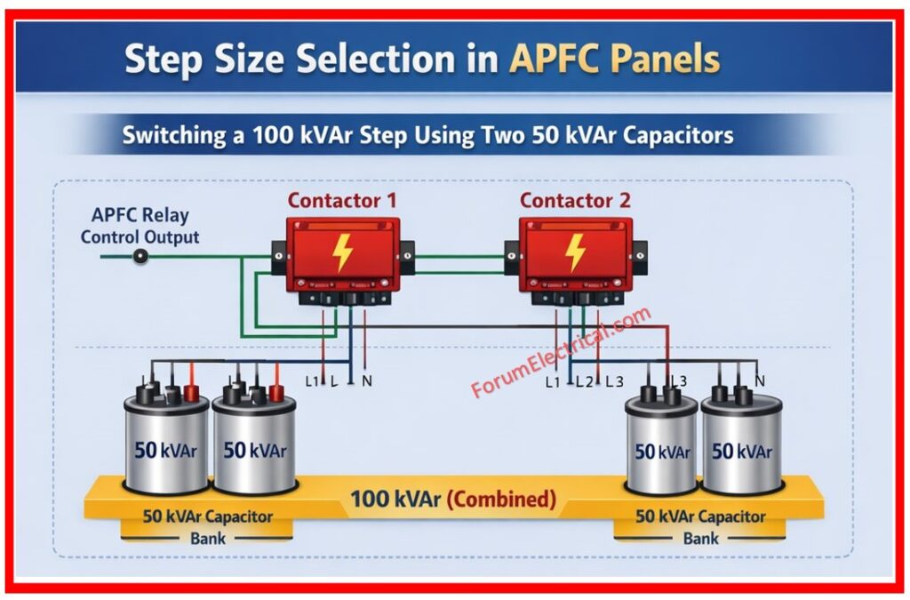
Maximum step size must be 100 kVAr.
Use capacitor duty contactors (or) thyristor switching modules.
Practically, utilize 2 x 50 kVAr banks in parallel for a 100 kVAr step.
Stage-2: Minimum Step Size Selection
Minimum step size determines accuracy of power factor (PF) correction.
APFC relay sensitivity ~2.5%.
Electricity boards consider power factor (PF) up to 0.99.
Ideal power factor (PF) range: 0.96 to 0.99.
Thumb Rule
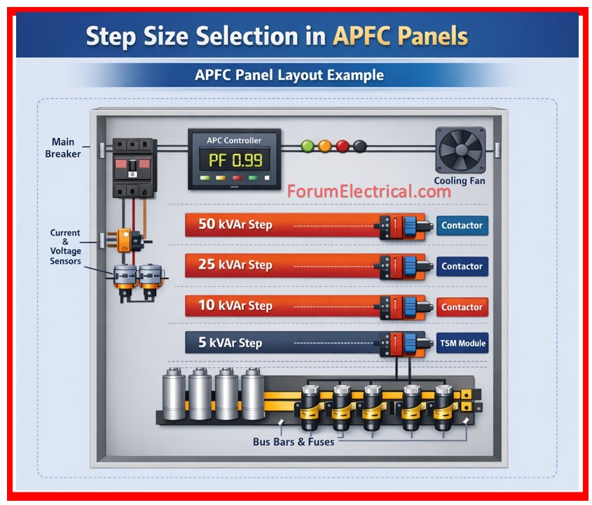
Minimum step size = 5% to 10% of total kVAr.
| Panel Size | Minimum Step |
| Up to 100 kVAr | 5 kVAr |
| 100–500 kVAr | 10–25 kVAr |
| 500–1000 kVAr | 25 kVAr |
Stage-3: Number of Steps in APFC Panels
Number of steps in APFC panels depends on controller technology and cost.
Conventional controllers need more steps.
Intelligent controllers allow for mixed step sizes and fewer steps.
Design Objectives
• Maximum electrical combinations.
• Minimum physical steps.
The number of steps must balance:
- Accuracy
- Cost
- Panel size
Controller Technology Impact
Conventional Controllers
- Need more steps
- Follow linear (or) circular switching
Advanced Controllers (Intelligent)
- Use optimized switching logic.
- Allow mixed step sizes.
- Reduce number of steps.
Stage-4: Design Objectives
An ideal APFC panel should have:
Maximum Electrical Steps
- Improves flexibility
- Enhances PF correction accuracy
Minimum Physical Steps
Reduces:
- Panel size
- Cost
- Maintenance
Stage-5: Step Configuration Examples
For 100 kVAr Panel
Case A:
- 10 steps of 10 kVAr
- 10 physical steps
- 10 electrical steps
Case B:
- 50 + 25 + 15 + 5 + 5
- 5 physical steps
- 20 electrical steps
Here, Case B is more efficient.
For 300 kVAr Panel
Case A:
- 25 kVAr x 12
- 12 physical steps
Case B:
- 100 + 3 x 50 + 2 x 25
- 6 physical steps
Case B reduces the hardware while maintaining performance.
For 600 kVAr Panel
Case A:
- 50 kVAr x 12
- 12 steps
Case B:
- 3 x 100 + 5 x 50 + 2 x 25
- 10 physical steps
- 24 electrical combinations
Case B provides higher resolution with fewer steps.
Stage-6: Step Combination Strategy
Large Steps (Up to 100 kVAr)
- Used for the base load compensation
Medium Steps
- Used for a variable load correction
Small Steps (5–10% or 25 kVAr)
- Used for the fine tuning
General Recommendations Table
| Panel Rating | Steps | Suggested Combination |
| 100 kVAr | 5 | 50 + 25 + 15 + 5 + 5 |
| 300 kVAr | 6 | 100 + 3 x 50 + 2 x 25 |
| 600 kVAr | 10 | 3 x 100 + 5 x 50 + 2 x 25 |
| 1000 kVAr | 12 | Mixed (100, 50, 25 kVAr) |
APFC Panel Step Size Selection Table
This table is primarily suitable for most of the industrial applications.
Final step selection should always be based on:
- Load profile study,
- Harmonic conditions and
- Switching technology.
| Panel Rating (kVAr) | Physical Step Size (kVAr) | No. of Physical Steps | Electrical / Logical Steps (kVAr) | No. of Electrical Steps |
|---|---|---|---|---|
| 35 | 2×12.5 + 2×5 | 4 | 5, 10, 12.5, 17.5, 22.5, 25, 30, 35 | 8 |
| 50 | 2×12.5 + 2×10 + 1×5 | 5 | 5, 10, 12.5, 15, 17.5, 20, 22.5, 25, 27.5, 30, 35, 37.5, 40, 45, 50 | 15 |
| 75 | 2×25 + 2×10 + 1×5 | 5 | 5, 10, 15, 20, 25, 30, 35, 40, 45, 50, 55, 70, 75 | 13 |
| 100 | 2×25 + 2×15 + 1×5 | 5 | 5, 10, 15, 20, 25, 30, 35, 40, 45, 50, 55, 95, 100 | 13 |
| 125 | 2×12.5 + 2×25 + 50 | 5 | 12.5, 25, 37.5, 50, 62.5, 75, 87.5, 100, 112.5, 125 | 10 |
| 150 | 2×12.5 + 2×25 + 50 | 6 | 12.5, 25, 37.5, 50, 62.5, 75, 87.5, 137.5, 150 | 12 |
| 175 | 2×12.5 + 2×25 + 50 | 6 | 12.5, 25, 37.5, 50, 62.5, 75, 87.5, 162.5, 175 | 14 |
| 200 | 2×12.5 + 2×25 + 50 | 6 | 12.5, 25, 37.5, 50, 62.5, 75, 87.5, 187.5, 200 | 16 |
| 225 | 2×12.5 + 2×25 + 50 | 6 | 12.5, 25, 37.5, 50, 62.5, 75, 87.5, 212.5, 225 | 18 |
| 250 | 4×50 + 2×25 | 6 | 25, 50, 75, 100, 125, 150, 175, 200, 225, 250 | 10 |
| 275 | 1×50 + 1×25 | 6 | 25, 50, 75, 100, 125, 150, 175, 200, 225, 250, 275 | 11 |
| 300 | 1×100 + 3×50 + 2×25 | 6 | 25, 50, 75, 100, 125, 150, 175, 200, 275, 300 | 12 |
| 350 | 1×100 + 3×50 + 4×25 | 8 | 25, 50, 75, 100, 125, 150, 175, 200, 325, 350 | 14 |
| 400 | 2×100 + 2×50 + 4×25 | 8 | 25, 50, 75, 100, 125, 150, 175, 200, 375, 400 | 16 |
| 450 | 2×100 + 3×50 + 2×25 | 8 | 25, 50, 75, 100, 125, 150, 175, 200, 425, 450 | 18 |
| 500 | 2×100 + 4×50 + 2×25 | 8 | 25, 50, 75, 100, 125, 150, 175, 200, 475, 500 | 20 |
| 550 | 3×100 + 3×50 + 2×25 | 10 | 25, 50, 75, 100, 125, 150, 175, 200, 525, 550 | 22 |
| 600 | 3×100 + 5×50 + 2×25 | 10 | 25, 50, 75, 100, 125, 150, 175, 200, 575, 600 | 24 |
| 650 | 4×100 + 4×50 + 2×25 | 10 | 25, 50, 75, 100, 125, 150, 175, 200, 625, 650 | 26 |
| 700 | 4×100 + 5×50 + 2×25 | 12 | 25, 50, 75, 100, 125, 150, 175, 200, 675, 700 | 28 |
| 750 | 5×100 + 3×50 + 2×25 | 12 | 25, 50, 75, 100, 125, 150, 175, 200, 725, 750 | 30 |
| 800 | 5×100 + 5×50 + 2×25 | 12 | 25, 50, 75, 100, 125, 150, 175, 200, 775, 800 | 32 |
| 850 | 6×100 + 4×50 + 2×25 | 12 | 25, 50, 75, 100, 125, 150, 175, 200, 825, 850 | 34 |
| 900 | 6×100 + 5×50 + 2×25 | 12 | 25, 50, 75, 100, 125, 150, 175, 200, 875, 900 | 36 |
| 950 | 7×100 + 4×50 + 2×25 | 12 | 25, 50, 75, 100, 125, 150, 175, 200, 925, 950 | 38 |
| 1000 | 8×100 + 2×50 + 2×25 | 12 | 25, 50, 75, 100, 125, 150, 175, 200, 975, 1000 | 40 |
Important Design Guidelines
- More steps do not always have a mean better performance
- Intelligent controllers reduce the required steps
- Always mix:
- Large
- Medium
- Small capacitors
- Avoid the overcompensation (leading PF)
- Also consider harmonic conditions
- Maximum step size must not exceed 100 kVAr
- Minimum step size must be 5–10% of total capacity
- Use a mixed step configuration
- Prefer intelligent APFC controllers
- Always analyze load profile before design
Conclusion
The optimum selection of capacitor step size and number of steps is essential for achieving an efficient and economical APFC panel performance.
A balanced combination of different step sizes that ensures an accurate
- Power factor correction,
- Reduced switching stress and
- Optimized system cost.
For better results detailed load analysis and modern controller selection are highly recommended.
