
MCCB Sizing Table
The MCCB sizing and selection table is an essential reference table used for selecting the appropriate Molded Case Circuit Breaker (MCCB) (or) Miniature Circuit Breaker (MCB) depending upon the connected electric load that is rated in kilowatts (kW).
- MCCB Sizing Table
- Purpose of the Table
- Load Analysis
- Breaker Selection
- Breaker Types
- Formula
- Solved Example
- Safety Considerations
- MCCB Selection Table (Enhanced with Load Factors)
- Chart Representation
- MCCB Selection Table (As per DEWA with Extended Load Factors)
- Load Analysis
- Safety Margin
- Standard Ratings
- Advantages
- Applications
- What is the 125% rule for breakers?
- What is the maximum range of MCCB?
- Conclusion
The table ensures a safe & reliable operation of electrical systems by incorporating the safety margins & a standard breaker ratings as per DEWA regulations.
Purpose of the Table
The table is detailed to simplify the selection of circuit breakers for a wide range of different electrical loads.
It helps engineers, electricians and designers to choose the correct protective device without complex calculations.
Load Analysis
The table starts with the base electrical load expressed in kilowatts.
Each load value represents the actual connected load in the system.
A 25% safety margin is added to the base load.
This additional margin ensures that the breaker does not trip under any normal fluctuations (or) temporary overload conditions.
Higher load factors such as 50%, 75% and 100% are also considered in the tables.
These values give flexibility for the future expansion in detail and their design considerations.
Breaker Selection
The adjusted load value is utilized to determine the appropriate breaker rating.
The standard MCCB rating is selected such that it is equal to (or) higher than the calculated load.
This ensures that the breaker operates safely without any nuisance tripping.
It also protects cables and equipment from the overload and short circuit conditions.
Breaker Types
Lower load applications typically use Miniature Circuit Breakers (MCBs).
These are applicable for small current ratings and residential (or) light commercial loads.
Higher load applications use Molded Case Circuit Breakers (MCCBs).
These are designed for the industrial and heavy duty applications with higher current ratings.
Formula
Current (A) = (Power (kW) x 1000) / (√3 x Voltage x Power Factor)
Solved Example
For 10 kW load at 415V and PF 0.8:
Given
Kw = 10 Kw
V = 415 V
PF = 0.8
Formula
Current (A) = (Power (kW) x 1000) / (√3 x Voltage x Power Factor)
Solution
Current (A) = (10 x 1000) / (√3 x 415 x 0.8)
Current ≈ 17.36 A
Answer
Select next standard MCCB = 20A.
Safety Considerations
The inclusion of a 25% safety margin improves the system reliability.
It prevents frequent tripping due to the minor load variations.
Proper breaker selection protects electrical equipment from damage.
It also enhances the overall safety of the electrical installation.
MCCB Selection Table (Enhanced with Load Factors)
| S. No | Load (kW) | 25% | 50% | 75% | 100% | 125% | MCCB (A) |
|---|---|---|---|---|---|---|---|
| 1 | 3.45 | 4.31 | 5.18 | 6.04 | 6.90 | 8.63 | 6 |
| 2 | 5.74 | 7.18 | 8.61 | 10.05 | 11.48 | 14.35 | 10 |
| 3 | 9.19 | 11.49 | 13.79 | 16.08 | 18.38 | 22.97 | 16 |
| 4 | 11.49 | 14.36 | 17.23 | 20.11 | 22.98 | 28.72 | 20 |
| 5 | 14.36 | 17.95 | 21.54 | 25.13 | 28.72 | 35.90 | 25 |
| 6 | 18.38 | 22.97 | 27.57 | 32.16 | 36.76 | 45.95 | 32 |
| 7 | 22.97 | 28.71 | 34.45 | 40.20 | 45.94 | 57.44 | 40 |
| 8 | 28.72 | 35.90 | 43.08 | 50.26 | 57.44 | 71.80 | 50 |
| 9 | 36.18 | 45.23 | 54.27 | 63.32 | 72.36 | 90.45 | 63 |
| 10 | 45.95 | 57.44 | 68.93 | 80.41 | 91.90 | 114.88 | 80 |
| 11 | 57.44 | 71.80 | 86.16 | 100.52 | 114.88 | 143.60 | 100 |
| 12 | 71.80 | 89.75 | 107.70 | 125.65 | 143.60 | 179.50 | 125 |
| 13 | 91.90 | 114.88 | 137.85 | 160.83 | 183.80 | 229.75 | 160 |
| 14 | 114.87 | 143.59 | 172.31 | 201.02 | 229.74 | 287.18 | 200 |
| 15 | 143.59 | 179.49 | 215.38 | 251.28 | 287.18 | 358.98 | 250 |
| 16 | 172.31 | 215.39 | 258.47 | 301.54 | 344.62 | 430.78 | 300 |
| 17 | 201.03 | 251.29 | 301.55 | 351.80 | 402.06 | 502.58 | 350 |
| 18 | 229.74 | 287.18 | 344.61 | 402.05 | 459.48 | 574.35 | 400 |
| 19 | 287.20 | 359.00 | 430.80 | 502.60 | 574.40 | 718.00 | 500 |
| 20 | 361.85 | 452.31 | 542.78 | 633.24 | 723.70 | 904.63 | 630 |
| 21 | 459.49 | 574.36 | 689.24 | 804.11 | 918.98 | 1148.73 | 800 |
Chart Representation
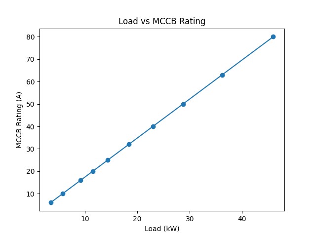
MCCB Selection Table (As per DEWA with Extended Load Factors)
Load Analysis
It calculates the necessary MCCB size based on the connected load in kilowatts (kW).
Safety Margin
A 25% safety factor is added to the initial load to determine the adjusted load requirement.
Standard Ratings
The table recommended standard MCCB rating in Amperes to be utilized based on that adjusted load.
These standards ensure uniformity & safety in electrical installations.
Using DEWA approved selection methods helps in obtaining approvals and maintaining compliance in projects.
| S.No | Load (kW) | 25% | 50% | 75% | 100% | 125% | MCCB (A) |
|---|---|---|---|---|---|---|---|
| 1 | 5.74 | 7.18 | 8.61 | 10.05 | 11.48 | 14.35 | 10 |
| 2 | 8.62 | 10.77 | 12.93 | 15.08 | 17.24 | 21.55 | 15 |
| 3 | 11.49 | 14.36 | 17.23 | 20.11 | 22.98 | 28.72 | 20 |
| 4 | 17.23 | 21.54 | 25.85 | 30.15 | 34.46 | 43.08 | 30 |
| 5 | 22.97 | 28.71 | 34.45 | 40.20 | 45.94 | 57.44 | 40 |
| 6 | 28.72 | 35.90 | 43.08 | 50.26 | 57.44 | 71.80 | 50 |
| 7 | 34.46 | 43.08 | 51.69 | 60.31 | 68.92 | 86.15 | 60 |
| 8 | 45.95 | 57.44 | 68.93 | 80.41 | 91.90 | 114.88 | 80 |
| 9 | 57.44 | 71.80 | 86.16 | 100.52 | 114.88 | 143.60 | 100 |
| 10 | 71.80 | 89.75 | 107.70 | 125.65 | 143.60 | 179.50 | 125 |
| 11 | 91.90 | 114.88 | 137.85 | 160.83 | 183.80 | 229.75 | 160 |
| 12 | 103.38 | 129.22 | 155.07 | 180.91 | 206.76 | 258.45 | 180 |
| 13 | 114.87 | 143.59 | 172.31 | 201.02 | 229.74 | 287.18 | 200 |
| 14 | 129.23 | 161.54 | 193.85 | 226.15 | 258.46 | 323.08 | 225 |
| 15 | 143.59 | 179.49 | 215.38 | 251.28 | 287.18 | 358.98 | 250 |
| 16 | 172.31 | 215.39 | 258.47 | 301.54 | 344.62 | 430.78 | 300 |
| 17 | 201.03 | 251.29 | 301.55 | 351.80 | 402.06 | 502.58 | 350 |
| 18 | 229.74 | 287.18 | 344.61 | 402.05 | 459.48 | 574.35 | 400 |
Advantages
- The table simplifies the design process.
- It reduces calculation errors and saves time.
- It ensures proper protection of electrical systems.
- It also provides a standardized method to breaker selection.
Applications
- The MCCB selection table is widely used in residential buildings.
- It is also used in commercial complexes and industrial facilities.
- It assists in panel design and load distribution planning.
- It is also useful in energy management and system upgrades.
What is the 125% rule for breakers?
The 125% Rule in Electrical Load is that electricians must understand and attain knowledge.
The 125% rule requires that
- Branch circuits,
- Feeders and
- Overcurrent protective devices (breakers)
for continuous loads (running 3 hours / more) be rated at 125% of the total load.
What is the maximum range of MCCB?
The maximum normal current rating of an MCB may technically range up to just 125A whereas the maximum normal current rating of an MCCB is usually much higher ranging from 16A to as high as an almost 1600A.
Conclusion
The MCCB selection and sizing table is an essential online tool for electrical engineers and technicians.
It provides a detailed, structured and reliable method for the purpose of selecting the right circuit breakers based on the load requirements and safety margins.
It ensures a safe operation, regulatory compliance & efficient electrical system design.