
- What is Corona Discharge?
- Corona Effect in Transmission Lines
- What is the Corona Effect?
- What is the Corona Effect of a Cable?
- Corona Power Loss Formula
- Factors Affecting Corona Power Loss
- How to reduce the Corona Effect?
- Advantages of Corona Effect
- Disadvantages of Corona Effect
- Direct Current (DC) Corona Discharge
- Differences Between Positive & Negative Corona Discharge
- What is the Ferranti Effect?
- What is the Skin Effect?
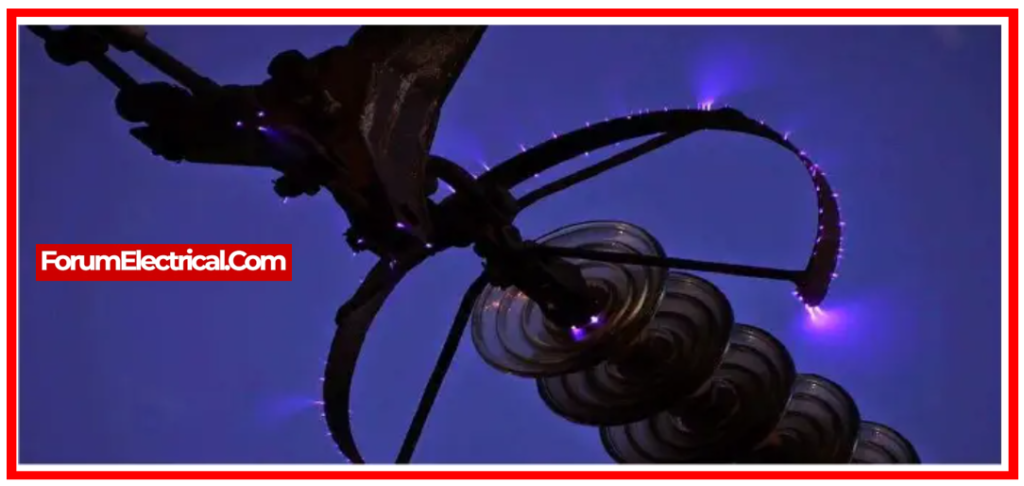
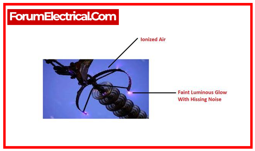
The corona effect, characterized by a hissing noise and a violet glow, is widely encountered in high voltage (HV) transmission lines.
Corona impacts cause a large voltage drop & energy loss, as well as the production of ozone gas. It is therefore essential to understand this phenomenon and its impact on the transmission system.
This post discusses the factors that contribute to the corona effect, its drawbacks, as well as some advantages and techniques for reducing it.
What is Corona Discharge?
Corona Discharge (or) Corona Effect refers to the ionization of the air surrounding high voltage transmission lines, which causes the conductors to light and produce a hissing noise.
Corona discharge depends on two factors:
- Alternating electrical potential variations must be applied across the line.
- The conductor spacing must be sufficiently large in comparison to the line diameter.
IEC 60815: This standard specifies how to select insulators for overhead wires depending on their resistance to electrical, thermal, & environmental stresses, such as corona discharge.
Corona Effect in Transmission Lines
Potential gradient is caused by the electrostatic field across transmission line conductors. Air is ionized when the conductor surface potential gradient reaches 30kV/cm at normal pressure & temperature.
Air surrounds transmission line wires. Air is dielectric.
During electric fields below 30kV/cm, the conductor’s induced current cannot ionize the air.
When air encircling the conductor surpasses 30kV/cm, charging current flows through the air, ionizing it.
As a virtual conductor, ionized air hisses and glows violet.
What is the Corona Effect?
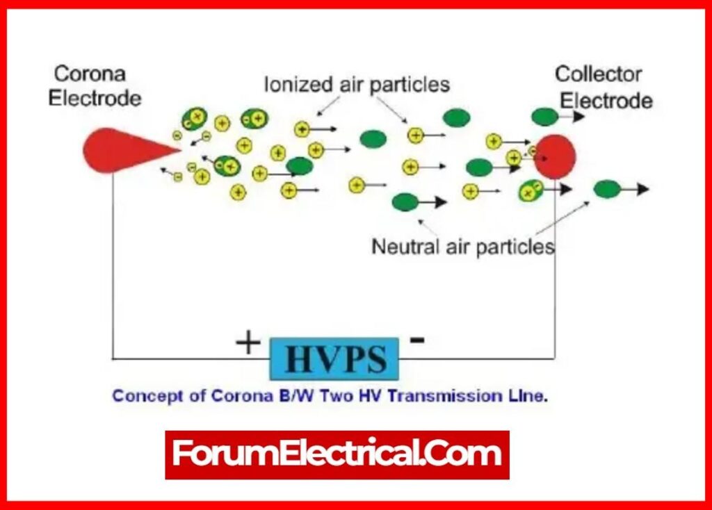
Due to its numerous free electrons and ions, air naturally produces the corona effect.
Free ions & electrons in air experience a force when two conductors create an electric field. This accelerates ions and free electrons in the opposite direction.
While moving, charged particles collide with one other and slow-moving uncharged molecules.
Thus, charged particles multiply quickly. If the electric field is high enough, air dielectric breakdown and arcing will occur between conductors.
Electric power transmission moves electricity from generating units to many kilometers from cities and consumption centers.
Long-distance transmission wires are essential for power transfer, which causes massive system losses.
Power engineers have struggled to reduce energy losses.
Corona discharge can drastically degrade power system EHV line efficiency.
IEEE Std 1313 outlines guidelines for reducing corona impacts in electric power systems.
What is the Corona Effect of a Cable?
The corona effect is a partial electrical discharge induced by the ionization of air around a conductor. It appears whenever the voltage surpasses a critical threshold but the conditions do not permit the development of an electric arc.
Corona Power Loss Formula
There are 2 formulas for calculating corona power loss.
- Peek’s Formula
- Peterson’s Formula
Peek’s Formula
PL = 241 X 10-5 [(f+25)/δ] (r/d)1/2 (VO-VC)2 KW/Km/Phase
Where,
PL – Corona Power Loss (KW/Km/Phase)
f – Supply Frequency (Hz)
r – Radius of the conductor (meters)
d – Distance between 2 adjacent conductors (meters)
V0 – operating voltage (kV)
VC – Critical disruptive voltage (kV)
d – Air density correction factor.
Visual critical voltage Vv is the minimal phase voltage at corona effect.
The critical voltage formula is:
Vv = g0 δ mv r [1+(0.3/√δr)] loge(d/r)
Where,
δ – Density factor of air
mv – Roughness factor
Note: Conductor surface smoothness is measured by this factor. Smooth conductors have unity. As conductor roughness increases, mv decreases.
d – Spacing between line conductors
r – Conductor radius
g0 – Dielectric strength of air
The disruptive critical voltage is mathematically expressed as follows:
VC = g0 δ m0 r loge(d/r)
It should be mentioned that for a single-phase line, VO equals
VO = (Line Voltage/2)
For a three-phase line, VO
VO = (Line Voltage/√3)
Peek’s Formula can be used in conditions of visual corona. When losses are low & VO/VC is less than 1.8, this formula typically produces incorrect results.
The value of m0 for different conductors:
| S.No | Conductor Surface | Irregularity Factor Value |
| 1 | Stranded Conductors | 0.8 – 0.87 |
| 2 | Dirty Conductors | 0.92 – 0.98 |
| 3 | Polished Conductors | 1 |
Peterson’s Formula
PL = [2.11 f F V02/{log10(D/r)}2] X 10-5 KW/Km/Phase
Where,
PL – Corona Power Loss (KW/Km/Phase)
f – Supply Frequency (Hz)
r – Radius of the conductor (meters)
d – Distance between 2 adjacent conductors (meters)
V0 -Voltage per phase (kV)
F (Factor) – Corona loss Function and it varies with ratio VO/VC.
F (Factor) Value:
| Vph/Vd0 | 0.6 | 0.8 | 1.0 | 1.2 | 1.4 | 1.6 | 1.8 | 2.0 | 2.2 |
| F(Factor) | 0.012 | 0.018 | 0.05 | 0.08 | 0.30 | 1.0 | 3.5 | 6.0 | 8.0 |
Factors Affecting Corona Power Loss
Corona power loss can be affected by the following reasons:
1). System Voltage
2). Density of Air
3). System Power Frequency
4). Conductor Radius
5). Conductivity of Air
6). Conductor’s Surface
7). Load Current
8). Atmospheric Condition
9). Bundling Conductors
10). Ground Clearance
1). System Voltage
When the voltage is higher, the electric field surrounding the conductors becomes stronger.
The greater voltage creates a strong electric field surrounding the conductor, which ionizes the surrounding air.
As a result, higher voltage leads to increased corona power loss.
The corona power loss equation shows that the rate of increase in power loss is moderate when Vph is close to Vd0, but when Vph is larger than Vd0, corona loss increases rapidly.
2). Density of Air
Corona loss decreases as air density increases.
Ex: Transmission lines running through a mountainous location will experience more power loss because of the corona than a line passing over flat ground since the density of air is lower in hilly areas.
3). System Power Frequency
According to Peek’s formula, the corona power loss is proportional to
PL ∝ (f+25)
As a result, the Corona Power loss is exactly proportional to the frequency. Corona loss rises with frequency.
4). Conductor Radius
The electric field intensity at conductor surface decreases with increasing conductor radius, resulting in less corona loss.
The smaller the diameter of the conductor, the greater the corona loss due to the high electric field intensity at the conductor surface.
5). Conductivity of Air
Stormy & rainy weather increases the concentration of ions in the atmosphere.
Consequently, the atmosphere becomes more conductive.
The higher the conductivity of the air, the more ions are present near the conductor surface. increased ions in the air result in increased corona loss.
The conductivity of air increases during the wet season, resulting in greater corona loss.
6). Conductor’s Surface
A stranded conductor has a higher corona loss because its surface potential gradient is greater than of a single equivalent conductor.
Corona power loss is greater for the rough surface conductor because a rough surface produces a large potential gradient.
7). Load Current
The flow of the load current in transmission lines causes the transmission line to heat up to some amount, which reduces the effect of corona loss by preventing the deposition of snow or dew on the conductor surface.
8). Atmospheric Condition
Corona loss is particularly noticeable during adverse weather circumstances, such as a cloudy or wet day.
9). Bundling Conductors
A bundled conductor has a far larger effective diameter than a single similar conductor.
The above corona power loss calculations show that bigger diameter values result in reduced corona power loss.
10). Ground Clearance
The height of the conductors above the ground also influences corona loss.
The lower the clearance of conductors from the ground, the greater the corona loss.
How to reduce the Corona Effect?
On substations or busbars rated for 33 kV or greater voltages, strongly ionized air can create flash-over in insulators (or) between the phases, causing significant damage to the equipment if the corona effect is not carefully designed.
The corona effect can be decreased using the following methods:
1). By increasing the Conductor’s Size
2). By increasing the Conductor Spacing
3). By Utilizing Corona Ring
4). Using Bundled Conductors
1). By increasing the Conductor’s Size
The voltage that causes corona arises can be increased by increasing the conductor size. Consequently, the corona effect can be decreased.
This represents one of the reasons why ACSR conductors with greater cross-sectional areas are employed in transmission lines.
2). By increasing the Conductor Spacing
The corona effect can be avoided by extending the distance between conductors, which increases the voltage at which the corona occurs.
However, increases in conductor spacing are limited due to the expense of supporting structures, as larger cross arms & supports accompanying increases in conductor spacing raise the cost of the transmission system.
3). By Utilizing Corona Ring
The intensity of the electric field is greatest when the conductor curvature is acute.
Corona discharge starts at sharp points, edges, & corners. Corona rings are used at the terminals of high-voltage equipment to reduce electric fields.
Corona rings are toroidal-shaped metallic rings that are fastened to the ends of bushings & insulator strings.

Because of its smooth round form, this metallic ring distributes charge over a wider area, lowering the potential gradient at the conductor’s surface below the crucial disruptive value and preventing corona discharge.
4). Using Bundled Conductors
Bundled conductors increases effective diameter of the conductor, which reduces the corona effect.
Advantages of Corona Effect
- As a result of corona crossing the conductor, the air sheath that envelops it becomes conductive, effectively increasing the conductor’s diameter.
- As a result of this virtual increase in conductor diameter, the maximal potential gradient or electrostatic stress is diminished.
- Due to this, the possibility of a flashover decreases.
- An additional advantage of the corona effect is that it mitigates the impacts of transients brought on by lightning & electrical surges.
- Induced charges on the line as a result of surge or other factors will undergo partial dissipation in the form of corona loss.
- Transmission lines are protected by Corona because it decreases the destructive effects of transients that are brought on by voltage surges.
Disadvantages of Corona Effect
- A non-sinusoidal voltage drop occurs along the transmission line as a result of non-sinusoidal corona current, causing interference with nearby communication circuits due to electromagnetic transients and electrostatic induction.
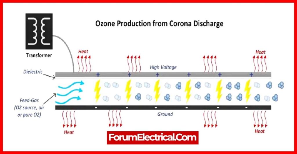
- Corona is accountable for the production of ozone gas, which is formed when it undergoes a chemical reaction with the conductor, resulting in corrosion.
- Corona loss refers to the amount of energy dissipated in a system as a result of the Corona effect.
- Corona-induced power loss is unwanted and uneconomical. The loss of electricity or energy significantly reduces the efficiency of the transmission line.
Direct Current (DC) Corona Discharge
Direct Current (DC) corona discharge has distinct characteristics and implications when compared to its alternating current (AC) substitute.
Fundamentals of Direct Current Corona Discharge
DC corona discharge is an experimental phenomenon that happens when a high voltage is delivered to an electrode system, which normally consists of
- An active electrode (usually sharp) and
- A passive electrode (commonly a flat surface),
in an atmosphere containing gaseous molecules, such as air.
The polarity of the DC voltage might be positive or negative, which influences the nature of the corona discharge.
DC Corona Discharge Characteristics
One of the distinguishing features of a DC corona discharge is their current-voltage correlation.
As the voltage delivered to the electrode system exceeds the onset voltage (the lowest voltage required for corona discharge to occur), the corona current increases.
Notably, the onset voltage of a DC corona discharge is affected by a variety of factors, including the form & size of the electrodes, the distance of the gap between the electrodes, & the gas properties in which the discharge occurs.
Differences Between Positive & Negative Corona Discharge
| Positive Corona Discharge | Negative Corona Discharge |
| The positive corona discharge normally produces a smooth, weak glow surrounding the active electrode. | The negative corona discharge produces a brighter, filamentary light that is largely focused in areas with the strongest electric fields. |
What is the Ferranti Effect?
Under no load conditions, the voltage at the receiving end of the transmission line exceeds the voltage at the sending end. This phenomenon is referred to as the Ferranti effect.
What is the Skin Effect?
The skin effect is the tendency of an alternating current (AC) to be distributed within a conductor in such a way that the current density is highest at the conductor’s surface and drops as depth increases.
