
Transformers serve a significant part in both the electrical grid & industrial processes.
What is Transformer Monitoring?
Transformer monitoring lowers corporate risk through:
- Improving safety for workers & the public
- Reducing unexpected failures.
- Reducing unforeseen outages.
The implications of an unanticipated transformer failure may be catastrophic, although many failures are avoidable.
A transformer’s condition is only as good as its worst-performing component.
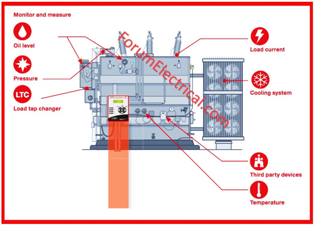
Transformer monitoring actively analyzes several operating aspects to ensure that they are working properly. Transformer monitors gather data and generate alerts to alert the consumer if something is wrong.
Transformer monitors can detect transformer failure symptoms by monitoring the cooling system,
- Load tap changer,
- Dissolved gas,
- Bushing power factor & capacitance,
- Partial discharge,
- Oil levels,
- Pressure,
- Temperatures, and other parameters.
Scope
The purpose of this monitoring is to analyze the many parameters of the transformer in order to forecast and avoid its failure.
Technical Details
Transformer Condition Monitoring is the process of collecting and processing data on numerous transformer parameters in order to forecast and avoid transformer failure.
This is accomplished by noting the departure of the transformer parameters from their predicted values.
Transformers are the most crucial components of the electrical transmission & distribution system. Transformer failures could result in power outages, individual & environmental risks, and costly rerouting or power purchase from other suppliers.
Transformer failures may occur owing to multiple types of reasons.
Transformer in-service interruptions and failures are typically caused by
- Dielectric breakdown,
- Winding distortion driven by short-circuit withstand,
- Winding & magnetic circuit hot spots,
- Electrical disturbances,
- Insulation deterioration,
- Lightning,
- Inadequate maintenance,
- Loose connections,
- Overloading, and
- Accessory failure such as OLTCs and bushings.
Need for Condition Monitoring
- Expensive capital equipment
- Difficult to repair or replace.
- Utilized advanced computer-aided design processes.
- Operation of transformers.
- Condition monitoring is essential.
- A corrective/preventative step can be taken.
Why do we need Condition Monitoring?
- Early detection of potential issues.
- Avoid a catastrophic outage.
- Support economic repair decisions. Maintenance Management.
- Measuring and analyzing trends to manage maintenance.
- The aging process & residual life are under control.
- Improve safety for personnel and the environment.
Purpose of Condition Monitoring
- To prevent forced outages
- Reduce failures
- Optimize maintenance expenses
What to Monitor?
- Winding resistance measures
- Measure capacitance, tan δ, insulation resistance (IR), & polarization index (PI).
- Oil parameters
- Dissolved Gas Analysis (DGA)
- FurfurAldehyde Analysis
- Degree of Polymerization (DP)
- Measurements for partial discharges (PD).
- Frequency Response Analysis (FRA) and
- Recovery Voltage Measurements.
- Understanding bushing capacitance and tan δ.
- Measure winding resistance and compare it to factory results.
- Increased resistance can indicate loose joints, hot spots, and contact erosion.
- Measure the capacitance & tan δ of windings and compare to factory results.
- Check for contamination, moisture absorption, insulation resistance (IR), and polarization index (PI).
- Measure IR and PI values for each winding in pairs & with respect to earth.
- Oil parameters.
- Compare to factory results.
- Lower values indicate inadequate insulation.
| PI (ratio of 10min to 1 min) | Condition |
|---|---|
| < 1 | Dangerous |
| Between 1.0 to 1.1 | Poor |
| Between 1.1 to 1.25 | Questionable |
| Between 1.25 to 2.0 | Fair |
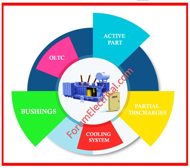
The key elements of transformer condition monitoring are:
- Thermal Modeling
- Dissolved Gas Analysis
- Frequency Response Analysis
- Partial Discharge Analysis
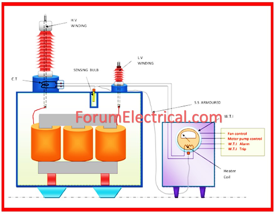
1). Thermal Modeling
A transformer’s useful life is defined in part by its capacity to dissipate internally generated heat onto its surroundings.
The comparison of actual and expected operating temperatures allows for an accurate diagnosis of the transformer’s condition and may reveal aberrant operation.
Temperature rise may have progressive impacts, as long as it remains within the break down limit.
Among these disadvantages, insulation deterioration is the economically significant. Insulation is really pricey. Its degradation is undesirable.
2). Dissolved Gas Analysis (DGA)
The transformer oil & solid insulating materials degrade, producing gasses.
Gasses are produced at a significantly faster pace when an electrical breakdown occurs.
Normal causes of fault gasses are divided into three types:
- Corona (or) partial discharge,
- Thermal heating, and
- Arcing.
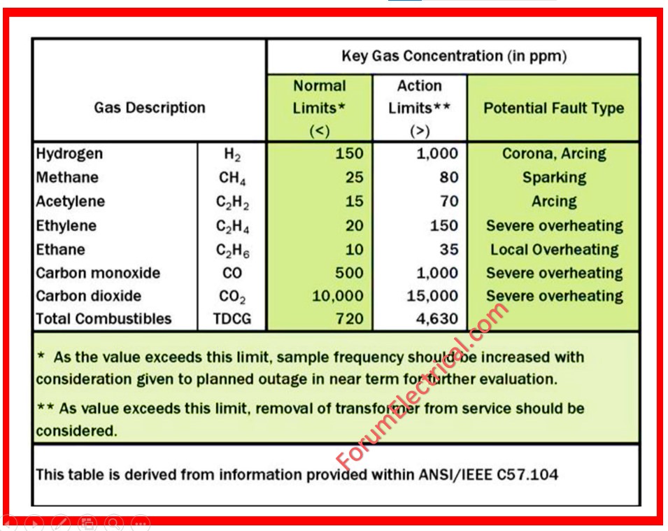
These problems can be detected by measuring the amounts of hydrocarbon gasses, hydrogen, and carbon oxides present in the transformer.
Different gasses can act as indicators of different types of problems.
Insulating materials in transformers & electrical equipment degrade, releasing gasses within the unit.
The distribution of these gasses can be linked to the type of electrical fault, & the rapidity of gas development can indicate the severity of the problem.
The identification of the gasses emitted by a certain unit can be quite important in any preventative maintenance plan.
The collection and measurement of gasses in an oil-insulated transformer was first described in 1928. By 2018, several years of empirical and theoretical research had gone into analysis of the transformer failure gasses.
Several gasses are produced during transformer gassing.
Nine gasses can provide enough important information, thus the remaining gasses are rarely studied.
The nine gasses analyzed include:
- Atmospheric gasses: nitrogen & oxygen.
- Carbon oxides: carbon monoxide & carbon dioxide.
- Hydrocarbons: methane, ethylene, acetylene, & ethane hydrogen
The gasses gathered from the sample oil are put into a gas chromatograph, which uses columns to separate gasses. The gasses are introduced into the chromatograph & passed through a column.
The column selectively retards the sample gasses, which are recognized as they pass through a detector at different periods. The chromatogram is a plot of the detector signal versus time.
Thermal conductivity detectors detect ambient gasses, while flame ionization detectors detect hydrocarbons and carbon oxides.
A methanator detects carbon oxides by converting them to methane at extremely low concentrations.
Types of Faults
Thermal Heating
Thermal failures can be detected by looking for byproducts of solid insulation degradation. The solid insulation is often made of cellulose fiber. The solid insulation degrades naturally, although the rate increases as temperature of insulation rises.
When an electrical fault occurs, energy is released, breaking the chemical bonds in the insulating fluid.
When the bonds are disrupted, these components rapidly rebuild the fault gasses.
The energies and speeds at which the gasses are generated vary for each gas, allowing the gas data to be evaluated to establish the type of faulting activity occurring within the electrical equipment.
Overheating windings often cause thermal breakdown of the cellulose insulation. In this case, the DGA results show elevated levels of carbon oxides (monoxide & dioxide). In extreme cases, methane & ethylene are discovered at elevated quantities.
Oil overheating causes the liquid to break down due to heat, resulting in the creation of methane, ethane, and ethylene.
Corona (or) Partial Discharge
Corona is a partial discharge identified in a DGA by high hydrogen levels.
Arcing
Arcing is the most serious fault condition in a transformer, and it can be detected at low levels of acetylene.
3). Frequency Response Analysis
When a transformer is subjected to high currents via fault currents, the mechanical structure & windings undergo extreme mechanical strains, resulting in winding movement and deformations.
It could also cause insulation degradation and turn-to-turn failures.
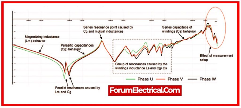
Frequency response analysis (FRA) is a non-intrusive, most sensitive technique for detecting winding movement problems and assessing deformation induced by loss of clamping pressure or short circuit stresses.
The FRA technique involves measuring the impedance of the transformer’s windings using a low voltage sine input that varies over a large frequency range.
4). Partial Discharge Analysis
Partial discharge (PD) happens when a local electric field surpasses a certain threshold, causing a partial breakdown of the adjacent medium. Its cumulative action degrades insulation.
PDs are caused by the existence of flaws during manufacturing or the option of increased stress due to design concerns.
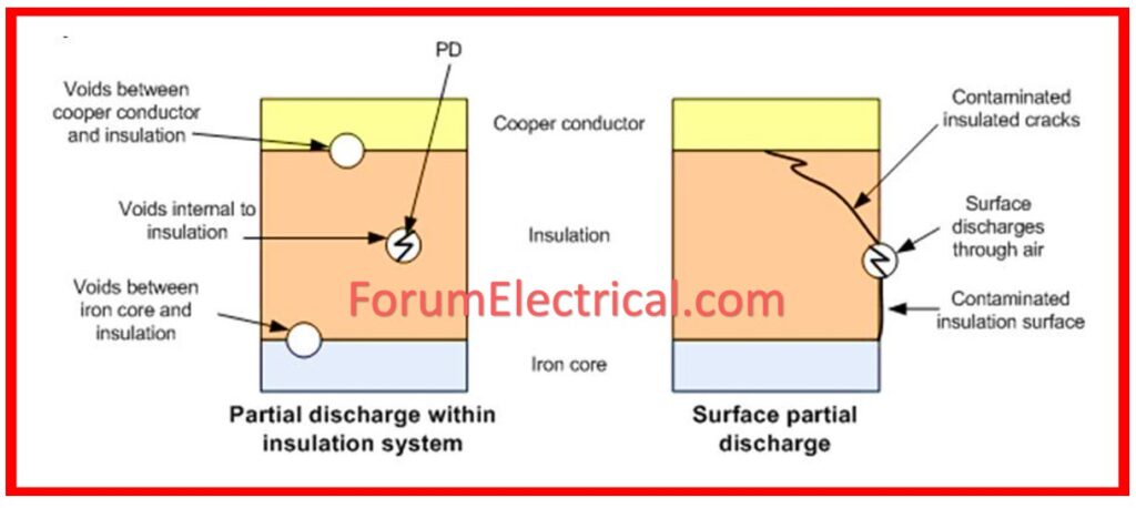
Measurements can be taken to detect these PDs and assess the strength of insulation.
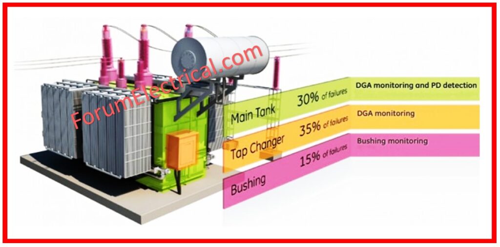
A typical condition monitoring system for an oil-immersed transformer can keep track of the status of numerous transformer components.
By using software to record and analyze measured data, the operator may be presented with data on the transformer’s state of health, as well as warnings when measured values surpass appropriate limits.
FAQS
1). What is a transformer and its function?
A transformer is a device that moves electrical energy from a circuit to another. Mutual induction is used to connect two circuits. It is also used to transfer electrical power via electromagnetic induction. Electricity is transmitted without any frequency change.
2). What is a transformer monitoring system?
Transformer monitors examine variations in transformers and associated electrical distribution systems by analyzing several factors in order to forecast and prevent transformer breakdown.
3). What is the method for monitoring of distribution transformer?
The Distribution Transformer Monitoring (DTM) system, also known as an intra-grid sensor, has a unique position within the distribution grid. It can provide real-time & historical data for the transformers it monitors.
4). What are condition monitoring tests for transformers?
Condition monitoring for transformers is the method of monitoring a transformer’s parameters (moisture, temperature, etc.) in order to detect a substantial change that indicates the development of a fault.
5). Why is transformer condition monitoring important?
Transformer monitoring decreases company risk by improving worker and public safety. reducing unexpected failures. Reducing unforeseen outages.


