
- Cable Testing
- Why is it required to Test Cables?
- What is carried out during Cable Testing?
- Different types of Cable Testing
- Type Test
- Physical Insulation and Sheath Tests
- Acceptance Test
- Routine Tests
- How do they conduct Cable Testing?
- Continuity Test
- Insulation Test
- Phasing Test
- Flammability Test
- Earth Resistance Test
- High Voltage Test
- Advantages of Cable Testing
- What is the standard for Cable Testing?
- Why is Cable Testing needed?
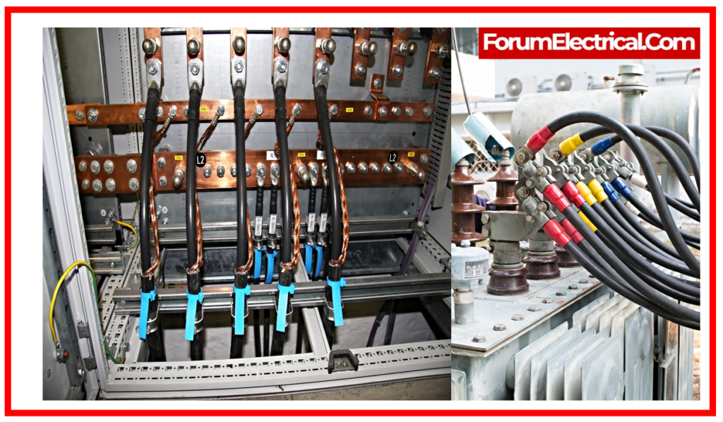
Cable Testing
Not all faults are evident like
- Crushing,
- Bending, or
- Kinking.
Your cabling installer should shield installed cabling against other workers. This is far cheaper than future cabling changes.
Before protecting cable routes that cannot be opened between termination & installation, terminate the cables so they can be tested.
Why is it required to Test Cables?
Cable testing reduces testing time. These checks:
- Cable uniformity
- Quality cabling
- Cable functionality
A cable issue is often visible before it turns into a problem. A visual assessment of the entire facility’s wires might detect issues before downtime. We check for copper corrosion, insulation cracks, cable wetness, and other cable damage signs.
Cable defects cost money and cause interruption; thus, cable test methods are in high demand to ensure cables and couplings are in a good condition and find cable faults quickly.
Cable testing to predict and fix errors is essential for electricity distributors. Cable testing can be difficult; however, many test methods and equipment can handle this issue.
Equally as important as test equipment is experience to assist choose and use it to get the best results.
What is carried out during Cable Testing?
- The following are the tests & inspections that should be performed prior to activating low voltage cable rated 600V or lower.
Compare cable data to drawings and specifications. - Pay close attention to the number of sets, cable size, routing, & insulation ratings. Mark these categories on the test sheet.
Examine uncovered sections of cable for the material damage. - Check the state of health of the cable jacket & the insulation of exposed areas.
- Check that the connection points match what is indicated on the project’s single-line diagram.
- Utilize a calibrated torque wrench or low-resistance ohmmeter to check bolted electrical connections for excessive resistance.
- When using a calibrated torque wrench, refer to ANSI/NETA Table 100.12 US Standard Fasteners.
- When using a low resistance ohmmeter, the values of identical bolted connections must be analyzed to see which one shifts by more than 50% of the smallest value.
- When visually inspecting low voltage wire and cable, pay attention to the condition of the exposing cable jacket & insulation.
- Inspect compression-applied connections to ensure that the connector is correctly rated for the installed cable size & has the necessary indentations.
- Perform an insulation resistance test on each conductor with regard to ground & adjacent conductors. The test period should be one minute, with a voltage set according to the manufacturer’s provided data.
- If no manufacturer literature is available, use 500 V DC for 300 V rated cable & 1000 V DC for 600 V rated cable.
- Insulation resistance values must correspond to the manufacturer’s published statistics. If no data from the manufacturer is available, the values need to be no less than 100 megohms.
- Conduct continuity tests to check proper cable connection and phasing.
- Use a low-resistance ohmmeter to ensure that parallel cables have consistent resistance.
- Measure the resistance of every cable individually and look for differences in resistance between the parallel conductors.
Different types of Cable Testing
Type Test
- Persulphate Test.
- Annealing Test.
- Tensile test (for aluminum).
- Wrapping Test (for Aluminum)
- Conductor Resistance Test.
- Test the thickness of insulation.
- Overall diameter measurement.
Physical Insulation and Sheath Tests
- Physical insulation and sheath tests include tensile strength and break elongation.
- Air oven ageing.
- Aging in an air bomb.
- Ageing in oxygen bomb.
- Hot set.
- Oil is resistant.
- Tear resistance.
- Resistant insulation
- Test for high voltage (water immersion).
- Flammability Test (only for SE-3, SE-4)
- Water abortion (insulation test)
Acceptance Test
- Annealing (copper) test
- Tensile test for aluminium
- Wrapping test (for aluminum
- Test for conductor resistance
- Test for insulation and sheath thickness, as well as overall diameter.
- Tensile strength & elongation at insulation and heat break.
- Insulation and sheath undergo hot set test.
- A high voltage tests
- Test for insulation resistance
Routine Tests
- Test for conductor resistance
- A high voltage tests
- Test for insulation resistance
How do they conduct Cable Testing?
Tests conducted during cable testing are listed below:
Continuity Test
Cable low resistance, measured in the range of 1 mΩ to 250 Ω, is determined by the continuity test, often known as low resistance measurement.
Depending on the amount of resistance to be measured, the continuity test can be performed with two or four wires: two wires for resistances greater than 1Ω and four wires for resistances less than 1Ω.
When conducting a continuity test in the two-wire mode, voltage & current at the resistance’s terminals are measured while a programmable current is injected. The specific amount can be found using Ohm’s law.
Dividing the switching matrix into two internal buses to route the test current carrying the voltage of the element under measurement’s terminals is known as the “four wires mode” or “Kelvin method” continuity test.
Odd addresses are assigned to current injection, and even addresses are assigned to the measurement’s sensitivity. When combined by 2 wire continuity tests, this arrangement can be implemented all the way across the switching matrix.
Insulation Test
A DC source is always used for the insulation test, commonly referred to as the high resistance test.
A short-circuit & high voltage test in DC are coupled with the insulation test.
There are multiple uses for the insulation test.
The insulation test can measure the strength of the dielectric and detect short circuits.
It can also determine insulation resistances between 50 kΩ and 2000MΩ at high voltage, or from 20V to 2000V.
The resistance of the cable is measured by the Megger after it has applied a high voltage to the insulation of the cable. It is also called Megger test. The higher the resistance, the better the insulation in the system. As a result of comparing the results to the norms, poor resistance may be an indication of problems.
Procedure for the Insulation Test
- To find any short circuit, conduct a low-voltage preliminary test (continuity measurement).
- If the insulation test finds a short circuit (the error list displays the message short circuit), the test is stopped.
- A high voltage is applied if there isn’t a short circuit.
- In the case that a breakdown happens during the programmable rise time, the test stops and the voltage is displayed (the breakdown voltage is provided in the error list).
- U<Uprog indicates in the error list if there is no breakdown and the voltage is below the necessary level (±10%).
- Next, for the period of the application time that has been programmed, the voltage is applied.
- The test will halt and the fault will be shown in the error list at the moment it manifests itself if a breakdown happens during this time.
- The insulating resistance is then tested at the conclusion of the application time, assuming everything goes according to plan.
- The tester will add a measurement time based on the required range.
- In accordance with range, the measurement duration ranges from 20 to 240 ms.
- The tester discharges the unit being tested to an earth resistance after lowering the high voltage (total time 20ms) to complete the sequence.
- Every insulation measurement process ends with the same process.
- The test for dielectric strength finds any abrupt changes in the test current’s growth outside of the predetermined range.
- Tests can be designed to exclude either the high voltage or short circuit tests.
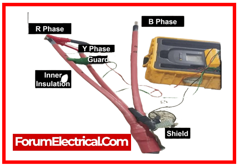
Phasing Test
Each location where LV cables are terminated into fuse bases or every place where an LV cable is run from one point to another must have its proper phasing audited.
Use of an instrument made specifically for the test is required. For this test, 240 volts of mains frequency voltage is unacceptable.
For this test, it is necessary to connect the neutral conductor to the earth stake.
Flammability Test
It is required that the duration of burning after the flame has been removed not exceed sixty seconds, and the distance between the lower edge of top clamp and the unaffected area must be at least 50 millimeters.
Under fire conditions, tests are performed on electric & optical fiber cables according to IEC 60332.
Earth Resistance Test
The earth resistance test for any overhead or subterranean network requires that, before connecting to the current network, the earth resistance at every point along the length of an LV feeder have a maximum resistance of 10Ω.
An earth resistance of less than 1Ω must exist before connecting to an existing network, whether it is underground (or) overhead line.
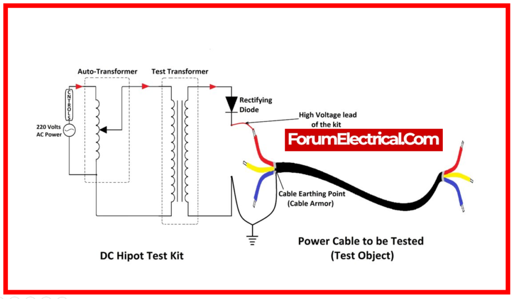
High Voltage Test
- Both AC and DC can be used for the high voltage test, commonly known as the hipot test or the dielectric strength test.
- Insulation is added if the high voltage test is conducted in DC; if it is conducted in AC, the sample is subjected to greater stress and gets formed.
- A 50Hz alternating voltage that can be adjusted to an effective 50V to 1500V is used to measure high voltage tests under alternating current.
- Similar to direct current, any abrupt increase in current up to a predetermined threshold is detected by the high voltage test.
- By default, the short circuit test is kept up to date. The application time is at least one period, and the rising time is greater than 500 ms.
Note: The capacitance value of the tested equipment penalizes the high voltage (HV) test under alternating current. The generator’s 5 mA maximum power must be kept in reference.
Advantages of Cable Testing
- Product warranties are prohibited.
- Testing is cheaper than repair.
- Periodic testing will future-proof the infrastructure.
What is the standard for Cable Testing?
For new cable circuits, a minimum testing duration of 60 minutes at 0.1 Hz is advised for installation or acceptance tests. If there is no failure and the observed feature stays steady for at least 15 minutes, a test duration of 15 to 30 minutes may be taken into consideration.
Why is Cable Testing needed?
- Crushing,
- Breaking, and
- Bending
are some of the most common cable faults.
These cable faults also have an impact on the equipment’s electrical performance. However, detecting them early can save you from major problems subsequently.
