
- What is Insulator Failure?
- Causes of the Insulator Failure
- Cracking of Insulator
- Defective Insulation Material
- Porosity in Insulation Materials
- Improper Glazing on the Insulator Surface
- Flash Over Across Insulator
- Mechanical Stresses on Insulators
- How electrical breakdown can occur in an Insulator?
- Insulator Testing
- Flashover Tests
- Performance Tests
- Routine Tests
- Why is Insulator Testing needed?
- What is the Megger Test?
- What is the formula for Insulator?
- What is the IEC standard for Insulators?
What is Insulator Failure?
Overvoltage and impulses cause electrical stress, which results in insulation failure. In this condition, the electric stress exceeds the electrical field strength of the insulation, resulting in a failure. This failure takes the form of
- Corona,
- Ionization, or
- Electric arcs.
Causes of the Insulator Failure
Failure of insulation in the electrical power system can occur for a wide range of reasons. Let’s explore them one by one.
- Cracking of Insulator
- Defective Insulation Material
- Porosity in Insulation Materials
- Improper Glazing on the Insulator Surface
- Flash Over Across Insulator
- Mechanical Stresses on Insulators
Cracking of Insulator
The porcelain insulator is primarily composed of three primary materials. The primary porcelain body, steel fitting arrangement, and cement to attach the steel section to the porcelain.
Because of changing climate conditions, the different materials in the insulator expand & contract at different rates.
- Unequal expansion & contraction of porcelain,
- Steel, and
- Cement
are the primary causes of insulator cracking.
Defective Insulation Material
If the insulation material utilized for the insulator is poor in any way, the insulator is more likely to be punched from that location.

Porosity in Insulation Materials
If the porcelain insulator is created at low temperatures, it will become porous, absorbing moisture from the air.
As a result, its insulation will decrease, and leakage current will begin to flow through the insulator, leading to its failure.
Improper Glazing on the Insulator Surface
If the surface of a porcelain insulator is not correctly glazed, moisture can accumulate on it. This wetness, together with deposited dust on insulator surface, creates a conducting pathway.
As a result, the insulator’s flashover distance is lowered. As the flash over distance decreases, the possibility of insulator failure due to flash over increases.
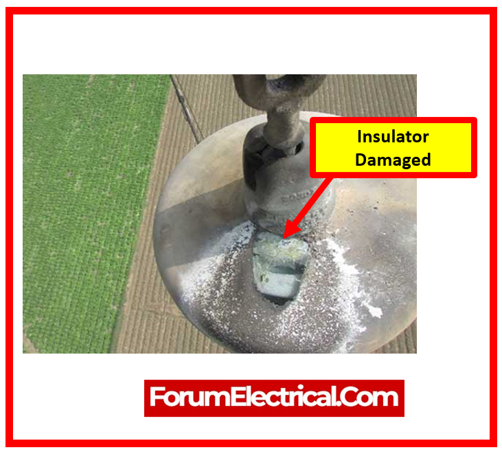
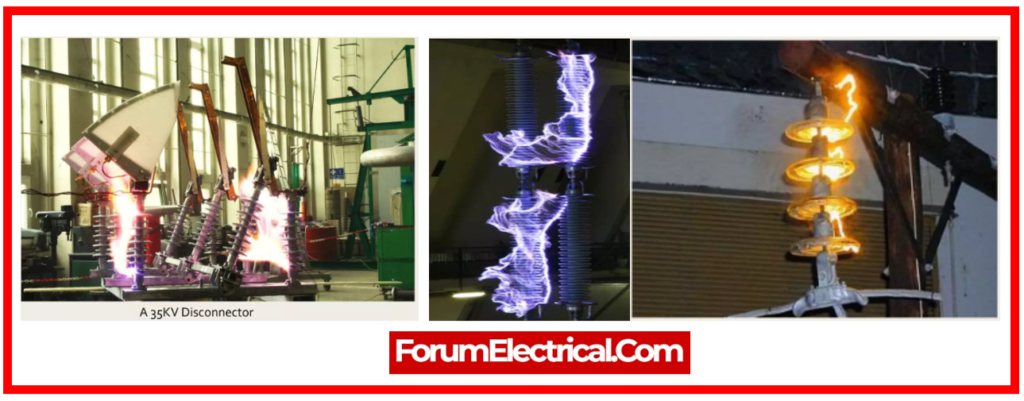
Flash Over Across Insulator
If a flashover occurs, the insulator may become overheated, resulting in its shuttering.
Mechanical Stresses on Insulators
If an insulator has a weak part due to a manufacturing error, it may shatter when mechanical stress is applied by its conductor.
These are the primary causes of insulation failure.
How electrical breakdown can occur in an Insulator?
Electrical breakdown of a substance happens when a high electric field is applied throughout an electrically insulating material, causing material ionization & current flow through the material.
Insulator Testing
The successful operation of a transmission (or) distribution line is heavily dependent on the proper functioning of insulators.
A good insulator must have adequate mechanical strength that can withstand mechanical loads and strains.
Its dielectric strength should be high enough to sustain operation and flashover voltages.
An insulator must also be clear of any pores or voids that could cause damage.
As a result, each insulator must go through a series of tests to ensure that it performs as expected.
We will now outline the various insulator test processes to ensure a low probability of failure of insulation.
In accordance with the British Standard, the electrical insulator has to go through the following tests:
- Flashover tests
- Performance tests
- Routine tests
Flashover Tests
It is also referred as insulator flashover tests.
Before an insulator is regarded to have undergone the flashover test, it goes through three types of tests.
- Power frequency dry flashover test
- Power frequency wet flashover test
- Impulse frequency flashover test
- Power frequency flashover voltage test
1). Power Frequency Dry Flashover Test
- The insulator to be tested is installed in the same way it will be utilized.
- The insulator’s electrodes are then connected to a variable voltage power frequency source.
- The voltage is steadily increased until it reaches the specified level.
- The provided voltage is smaller than the minimal flashover voltage. The voltage at which the surrounding air of insulator breaks down & becomes conductive is referred to as flashover voltage.
- The insulator must be able to sustain the specified voltage for sixty seconds (1 minute) without flashover.
2). Power Frequency Wet Flashover Test (Rain Test)
- In this test, the insulator to be tested is also installed in the same manner as it would be utilized.
- A variable voltage power frequency source is attached between the electrodes, as in the previous test.
- In addition, in this test, the insulator is sprayed with water at a 45° angle so that the precipitation rate does not exceed 5.08 mm/min.
- The voltage is subsequently increased to the specified level. The voltage is held at the prescribed level for 30 seconds (or) one minute, and the insulator is checked for punctures or breakdown.
- This test is also known as the one-minute rain test since it maintains a voltage for one minute.
3). Impulse Frequency Flashover Test
- This test is designed to determine that the insulator can withstand high voltage surges induced by lightning.
- The insulator being tested is installed in the same way as in previous testing. An impulse voltage generator is attached to the insulator, producing an extremely high voltage at a frequency of a few hundred kilohertz (kHz).
- This voltage is delivered to the insulator & the spark-over voltage is measured.
- The impulse ratio is the ratio of the impulse spark-over voltage to the spark-over voltage at power frequency.
- This ratio should be around
- 1.4 for pin type insulators &
- 1.3 for suspension type insulators.
Impulse Ratio = (Impulse Frequency Flashover Voltage/Power Frequency Flashover Voltage)

4). Power Frequency Flashover Voltage Test
- The insulator is maintained in the same way as in the previous test.
- In this test, the applied voltage is steadily increased, similar to prior tests.
- However, the voltage in which the surrounding air breakdown is recorded.
Performance Tests
Insulator performance tests evaluate electrical resistance, dielectric strength, & leakage current to ensure adequate isolation and longevity in electrical systems, hence providing safety and dependability.
The tests include are:
- Temperature Cycle Test
- Puncture voltage tests
- Mechanical Strength Test
- Electromechanical test
- Porosity test
1). Temperature Cycle Test
- In this test, the insulator is heated in water at 70° for an hour.
- The insulator is then promptly cooled to 7° for an additional hour.
- The cycle is repeated 3 times. The insulator is then dried, and the glazing is extensively examined for corrosion or degradation.

2). Puncture Voltage Test
- The objective of this test is to identify the puncture voltage.
- The insulator being tested remains suspended in the insulating oil.
- A voltage is applied & steadily increased until the perforation occurs. The voltage at which the insulator starts puncture is referred to as puncture voltage.
- This voltage is typically 30% greater than the dry flash-over voltage for suspension type insulators.
3). Mechanical Strength Test
- In this test, the insulator being tested is subjected to 250% of its maximum working load for a minute.
- This test determines the insulator’s ultimate mechanical strength.
4). Electromechanical Test
- This test is exclusively used for the suspension type insulators.
- In this test, the insulator is subjected to 250% of its maximum working tensile stress.
- Following that, the insulator is tested at 75% dry spark-over voltage.
5). Porosity Test
- This test involves breaking up a freshly made insulator sample.
- These pieces are then immersed in a 0.5% to 1% alcohol solution fuchsine dye (crimson red color) (C20H19N3·HCl) under 150 kg/cm2 pressure for several hours (say 24 hours).
- The pieces are then taken from the solution & checked for dye penetration.
- This test measures the degree of the porosity.
Routine Tests
Insulators are subjected to conventional voltage levels during routine testing to ensure they can endure regular working conditions, validating their electrical integrity & reliability in electric systems.
These tests assist in identifying any faults (or) weaknesses that might lead to the insulation failure and the tests include are:
- High Voltage Test
- Proof Load Test
- Corrosion Test
1). High Voltage Test
- This test is frequently performed on pin insulators.
- In this test, the insulator is inverted & immersed in water up to the neck.
- The spindle hole is likewise filled with water, & a high voltage is applied for five minutes.
- The insulator should be unharmed after this test.
2). Proof Load Test
- In this test, each insulator is subjected to a mechanical load that is 20% greater than its working load (for example, tensile force), for one minute.
- The insulator should be unharmed after this test.
3). Corrosion Test
- In this test, the insulator and metal fitting are immersed in a copper sulfate solution for a minute.
- The insulator is then taken from the solution, wiped, and cleaned.
- The operation is done four times.
- Then the insulator is inspected for metal deposits.
- There should be no metal deposits on insulator.
Why is Insulator Testing needed?
Electrical insulation is one of the most important parts of any structure or system because insulators help in the resistance to shock and short circuits. This also means that in order to take the necessary precautions, you need to have an accurate understanding of the resistance levels, which makes measuring resistance very important.
What is the Megger Test?
The Megger test is a method of testing that uses an insulation tester resistance meter to determine the state of electrical insulation. An electrical system’s insulation resistance declines with time and environmental conditions such as temperature, humidity, moisture, and dust particles.
What is the formula for Insulator?
A formula for calculating insulation resistance, known as R(ins), can be utilized in order to determine the insulation resistance.
R(ins) = V / I
What is the IEC standard for Insulators?
All insulators are developed and tested in accordance with IEC 60168, IEC 60273, & IEC 60815 and can be obtained upon request. Several standard creep ratings are mentioned. Units must meet the minimum creep requirements listed below for the pollutant severity classes specified in IEC 600815-1.