
- Transmission Line Systems
- Cause Factors
- How to Protect Transmission Lines?
- Applicable Standards
- Different types of Protection of Transmission Lines
- Overload Protection of Transmission Lines
- Overcurrent & Earth-Fault Protection of Transmission Lines
- Current-Graded Protection of Transmission Lines
- Differential Pilot-Wire Protection of Transmission Lines
- Current Balance Differential Protection of Transmission Lines
- Merz-Price Voltage Balance System of Transmission Lines
- Translay Protection System
- Split-Conductor Protection of Feeders
- Microwave Channel Protection of Transmission Lines
- Carrier Aided Distance Protection of Transmission Lines
- Power Swings of Transmission Lines
- Auto-Reclosing of Transmission Lines
Power transmission line protection systems are one of the most important structures in the electrical power system. A transmission system connects generators and distribution centers.
In this post, we will cover numerous aspects that have an impact on the protection of high voltage transmission lines.
Transmission Line Systems
Electrical power transmission line systems can be classified based on their type of current. The two most common types of electricity used are
- Direct Current (DC )and
- Alternative Current (AC).
The transmission lines are classified as follows based on the kind of current supply.
High Voltage Direct Current (HVDC) System
HVDC power transmission systems are widely employed for power transmission over very long distances.
High Voltage Alternating Current (HVAC) System
HVAC power transmission systems are substantially more affordable for short-distance power transmission.
Cause Factors
There are various aspects to consider when protecting transmission lines. The following are the factors that have an effect on protection.
- Wind and Ice
- Contamination
- Vandalism
- External forces
- Equipment Failures
- System disturbances
- Overloading the system and lightning.
These elements play a major part in the protection of transmission towers & electrical cables.
How to Protect Transmission Lines?
There are numerous protection methods for transmission lines, which can be divided into two categories:
- Non-Unit Type and
- Unit Type.
Non-unit type protection includes
- Time-Graded Overcurrent Protection,
- Current-Graded Overcurrent Protection, and
- Distance Protection,
whereas,
Unit type protection includes
- Pilot-Wire Differential Protection,
- Carrier-Current Protection based on phase comparison, and so on.
Ground faults require separate protection systems because they occur more frequently on overhead transmission lines than phase faults, and their magnitude differs from phase fault current.
The selection of a certain system of protection depends on the following factors:
- Economic justification for the strategy to achieve 100% supply continuity.
- Types of feeders: radial and ring mains.
- Accessibility of pilot wires.
- The number of switching stations connected in series between the supply and distant ends of the system.
- System earthing determines whether the neutral is grounded (or) insulated.
Applicable Standards
- IEEE C37.2: specifies standardized function numbers for protective relays utilized in power systems.
- IEEE C37.91: IEEE Guide for Protective Relay Applications to Transmission Lines, which gives information on the use of protective relays on transmission lines.
- IEC 60255: Measuring Relays and Protection Equipment series addresses many elements of protective relays & related equipment utilized in power systems.
Different types of Protection of Transmission Lines
There are 12 types of Protection of Transmission Lines
- Overload Protection of Transmission Lines
- Overcurrent & Earth-Fault Protection of Transmission Lines
- Current-Graded Protection of Transmission Lines
- Differential Pilot-Wire Protection of Transmission Lines
- Current Balance Differential Protection of Transmission Lines
- Merz-Price Voltage Balance System of Transmission Lines
- Translay Protection System
- Split-Conductor Protection of Feeders
- Microwave Channel Protection of Transmission Lines
- Carrier Aided Distance Protection of Transmission Lines
- Power Swings of Transmission Lines
- Auto-Reclosing of Transmission Lines
Overload Protection of Transmission Lines
Commonly used as the simplest method of line protection. Overload (or) overcurrent protection is used because a short circuit will increase the fault current several times the maximum load current.
The minimal fault current to maximum load current ratio is used to prevent fault operation during normal operating conditions. Its protection only works for simple systems.
Supply-end overcurrent protection is provided.
The below image shows feeder overload protection.

Three relay coils are connected to three CTs, one on each feeder phase.
Relays’ solenoid plunger systems close the trip coil circuit, which opens the circuit breaker and disconnects the protected feeder when overloading.
When the system changes, the relays must be adjusted or replaced. Typical operation times are long.
The well-known Z-connection protects a 3-phase circuit using two relays for overload (or) overcurrent protection.
Overcurrent & Earth-Fault Protection of Transmission Lines
Two or three overcurrent relays are usually used to defend against phase-to-phase faults & one for line-to-ground faults.
Independent earth fault relays are favored because they may be modified to protect single line-to-ground failures faster and more sensitively than phase relays.
Earth fault current is dependent on neutral earthing: securely earthed, insulated, or earthed by resistance or reactance.
When no neutral point exists, a grounding transformer is used.
Earth-fault currents are minimal compared to phase-fault currents regardless of neutral earthing type.
The relay for earth fault protection is different from phase-to-phase fault relays.
Overcurrent elements in residual circuits of CTs are preferable in resistance or securely earthed systems. Earth-fault relays can be set below line full-load current. Relays with a 10–40% setting range are used.
When 300/5 A CT is set to 20%, the relay operates for 12 A of primary earth-fault current.
Two IDMT overcurrent relays are attached in 2 phases through CTs & one earth-fault relay in the mentioned above safety method.
IDMT relays trip the circuit breaker for phase-to-phase or overload failures. Healthy CTs have zero total of three currents, hence the earth-fault relay is inactive.
Unbalanced currents trigger the earth-fault relay, which trips the circuit breaker during phase-to-ground faults.
For radial feeder earth fault prevention, time-grading is preferred due to inverse earth-fault elements.
This design provides main protection for 11 kV and 33 kV systems and backup protection for EHV transformers and transmission lines.
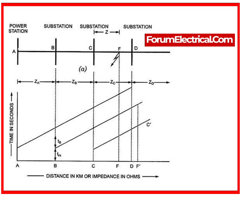
Current-Graded Protection of Transmission Lines
When the impedance among two substations is sufficient, current-graded protection can be used as an alternative or in addition to time-graded protection for transmission lines.
It utilizes the fact that the protected circuit’s short-circuit current reduces with distance from the supply end to the fault point.
The graded time lag system’s long delays can be somewhat mitigated by setting the relays to operate at a higher current towards supply end. This is current grading.
High-speed high-set overcurrent relays are used in current-graded systems.
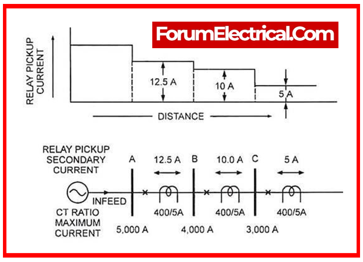
The above image shows a simple current-graded radial feeder protection arrangement.
It uses high-set overcurrent relays at A, B, and C to detect faults between A and B, B and C, and beyond C. The current setting decreases from supply to remote line termination.
- If a fault is near station B in section BC, the relay at A may perceive it as in section AB due to small fault current differences. This is because relays cannot distinguish between faults in the next section and the end of the first section.
- Reasons for this include:
- Small fault current differences,
- Uncertain fault current magnitude, and
- Different relay accuracy under transient situations.
- Therefore, relays protect just 80% of the line for discrimination. Current grading alone cannot safeguard, hence time-graded inverse definite minimum time (IDMT) relays should be used.
- Relay configuration might be difficult due to varying fault currents for different fault kinds.
- A system lacking directional control is unsuitable for ring mains, parallel feeders, & interconnected systems where power can flow in either direction to the problem.
Differential Pilot-Wire Protection of Transmission Lines
The term “pilot” refers to a channel that transmits information between transmission line ends. Three types of such channels are used:
- Wire pilot,
- Carrier-current pilot, and
- Microwave pilot.
Wire pilots are two-wire telephone-line circuits, either open or cabled.
Wire pilots are economical up to 8 or 15 kilometers, then carrier-current pilots are more cost-effective.
When pilot channels surpass the carrier current’s technical or economic capabilities, microwave pilots are used.
Differential pilot-wire protection is the most popular due to its simplicity, flexibility, high stability ratio, and rapid fault clearance (0.1 to 0.5 seconds depending on the circuit breaker’s “break time”).
Differential pilot-wire protection works on the idea that pilot wires should compare currents at each end of a line or feeder evenly under normal operating conditions & only lose equality when there is a breakdown.
Pilot wire length is the only variation between the alternator and transformer protection system.
Current Balance Differential Protection of Transmission Lines
Biased differential protection using McColl is an example of current balancing differential protection for transmission lines.
Consider single-phase feeder protection to comprehend its principle.
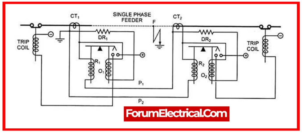
The shielded line ends have current transformers CT1 and CT2. Restraining coils R1 & R2 & pilot wires P1 & P2 connect the CTs’ secondaries. According to the illustration, diverting resistances DR1 & DR2 connect the relay operational coils to the CT secondaries.
These diverting resistances match pilot wire resistance, thus the operational coils O1 and O2 will get the same current.
With equal turns on the restraining and working coils, the beam relay sides will pull equally. Move the fulcrum toward the operational coil to give mechanical biasing and allow 10–12% more current to flow in the coil before it closes connections.
For a point F earth fault, CT1 will have more current than CT2. The secondary current of CT1 will flow in two parallel paths: diverting resistance DR1 and operating coil O1, and restraining coil R1, pilot-wire P1, diverting resistance DR2, operating coil O2, and restraining coil R2.
The second path (3 coils, 2 pilot-wires, and 1 diverting resistance) has 3 times the resistance of the first path. Thus, O1 will receive three-quarters of the current and R1 one-fourth. If the working coil O1 current surpasses the relay setting, the feeder is removed from supply.
Merz-Price Voltage Balance System of Transmission Lines
The Merz-Price differential feeder protection system uses voltage balance. In 3-phase systems, each conductor has two
- Current transformers &
- Relays.
Pilot wires connect current transformer secondaries in series.
In normal conditions, which means no feeder fault, equal currents flow at both ends, hence current transformer secondaries have identical induced voltages.
Secondary emfs are equalized when secondaries are linked in opposition, therefore relays have no circulating current.
When a fault occurs, currents differ at both ends, therefore induced emfs in current transformer secondaries differ and circulating current flows through pilot wires and relays, isolating the damaged feeder.
The current transformers are essential to this system because they must be balanced initially and permanently. Distributed air gap CT prevent magnetic circuit saturation, ensuring that the induced voltage is proportionate to line current.
The CTs are balanced against a standard to assure initial matching, and they are contained in a magnetic shield to prevent neighboring iron from altering flux distribution in service. Pilot wires are normally 7/0.73 mm 3-core cables.
Translay Protection System
Since the relay incorporates a transformer feature, the name “Translay” has been developed. Feeders with a tee-off, transformer feeders, single- or three-phase feeders, and parallel feeders can all be protected against phase and earth faults using this technique.
The foundation of this system is the well-established idea that the current flowing through a feeder at one end is always equal to the current exiting at the other.
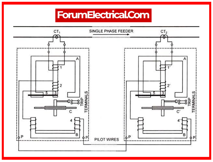
The diagram illustrates a basic type of Translay protection for a single phase feeder. The line current transformers CT1 & CT2, which are located at opposite ends of the feeder, carry equal currents under normal circumstances.
As a result, the coils 1 and 1′ that are linked to them because equal emfs to be induced in the corresponding windings 2 and 2′.
Split-Conductor Protection of Feeders
This system provides balanced protection without pilot wires. Two conductors of identical length and impedance interconnected in parallel will distribute the load evenly if the system insulation is good.
A problem on one conductor will carry more current over the other, which operates a relay to isolate the faulty line.
This technique protects each line phase by splitting it into two equal-impedance parts.
Light insulation separates the parts. This method uses single-turn current transformers at each split conductor end. Laminated iron rings with secondary windings around the periphery make up CT.
Due to the equal current flowing down the two splits, which are routed through the CT1 & CT2 in opposing directions, the voltage between the evenly dispersed secondary winding terminals is zero under healthy conditions.
Fault conditions cause one split to take more current than the other, unbalancing the primary side of CT.
Because of unbalanced currents on primary side of CT, flux will be set up in the core of one and induced in the uniformly spread secondary, energizing the relay coil R.
Relay contacts will close and the trip coil will trip circuit breaker to isolate fault.
Splits are best carried into circuit breakers on either side of the feeder to open them. Let the splits not enter the circuit breakers & a fault develops at the long line’s receiving end.
The differential current transformer’s end impedance may not be enough to balance the split conductor currents under these conditions. This fault will not be removed by the circuit breakers as the relay will not activate.
However, when splits are carried into circuit breakers, the fault current is limited to the faulty split after sending end tripped.
The transmitting end circuit breaker trips, but the fault current divides almost equally across the two solidly linked splits, therefore receiving end circuit breaker does not trip. When the fault current is limited to the faulty split, the receiving end circuit breaker opens.
Microwave Channel Protection of Transmission Lines
Microwaves are employed for all kind of protection aside from power line carrier (or) pilot-wire. Transmission is usually by line of sight, which must account for earth curvature and route topology. The simplest microwave channel can only be 40–60 kilometers long.
The relaying equipment at the protected line terminals is connected using an ultra-high frequency (450 MHz – 10,000 MHz) transmitter-receiver system. Space is the communication medium, hence the line does not require additional equipment. Receiver and transmitter are controlled like carrier-current transmitter & receiver.
For radio links (microwave pilots), line-of-light antennas transmit signals. Though pricey, these provide speedy, reliable service. The US uses radio communications for communication, remote control, and protection.
Carrier Aided Distance Protection of Transmission Lines
Currently used directional comparison carrier-pilot relay techniques use three-zone step-type distance relays. Internally zone 2 fault clearance is accelerated.
The carrier channel transmits a stabilizing signal to prevent a distant circuit breaker from tripping of a local exterior zone 2 fault or a tripping signal for an inner zone 2 fault.
Power Swings of Transmission Lines
Generators oscillate relative to each other owing to load changes, switching, or malfunctions, causing power fluctuations. A strong swing may not necessarily indicate instability of system. Identifying and responding to a defect and power swing is essential for the relay.
Due to their narrow properties, mho distance relays are less subject to power swings. Out-of-slip blocking relays usually work during power swings. TRIPS are allowed if the measuring element works within a certain duration after blocking relay operation. Distance relays nowadays are stable throughout an extensive range of power swings and do not trip if power returns to normal fast. If it persists, relay trips.
Auto-Reclosing of Transmission Lines
Most overhead transmission line faults are temporary. Statistics demonstrate that lightning, birds, tree branches, etc. generate 90% of defects. The fault energy input can be discontinued for a brief time to eliminate arcing faults and re-energize the line.
This underpins auto-reclosure, following relays at both ends of the line pick up, and circuit breakers get tripped as many times as possible at the same time & reclosed following deionization. Short-term faults disappear, and line service is entirely restored after reclosure. Double (or) triple isolation & reclosure can be done if the fault persists. If the problem persists, the breaker may stay open until reset manually.