
Testing and commissioning are key steps in the development of electrical power systems that ensure the continuous operation and dependability of vital infrastructure.
- Understanding Testing in Electrical Power Systems
- Commissioning of Electrical Power Systems
- Pre-Commissioning Procedures & Techniques
- Power Transformer Commissioning
- Surge Arrester Test
- Current Transformer (CT) Commissioning Test
- Voltage Transformer (VT) or Potential Transformer (PT) Commissioning Test
- Gas-Insulated Switchgear (GIS) Commissioning Test
- High-Voltage Cable Commissioning Test
- Protection & Control Panels Commissioning Test
- Final Energization Commissioning Procedures
- AC Distribution Panel Commissioning Test
- DC Distribution Panel Commissioning Test
- Battery Commissioning Test
- Battery Charger Commissioning Test
- Testing References
- Advantages of Commissioning Power Systems
These processes are essential for identifying and resolving potential issues prior a system goes live, protecting against failures and ensuring optimal performance, and serving as a useful reference for subsequent maintenance and operation.
Understanding Testing in Electrical Power Systems
Electrical power systems are made up of a complex interaction of components, including generators, transformers, and distribution networks. Testing entails thoroughly inspecting each component to ensure compliance with design specifications & standards. Key testing components include:
1). Dielectric Strength Testing: Determines the insulation strength of components to prevent electrical failures.
2). Functionality Testing: Verifies that each component performs as expected under normal & abnormal settings.
3). Protection Relay Testing: Determines the ability of protection systems to avoid equipment damage and maintain system stability.
Commissioning of Electrical Power Systems
Commissioning is the final stage in which different components are combined to create a fully operating power system. This includes:
1). System Integration: Enables seamless communication and coordination among multiple components, such as generators, switchgear, & control systems.
2). Load Testing: Assesses the system’s performance across various load circumstances to ensure it can manage peak demand while maintaining stability.
3). Relay Calibration: Fine-tunes protective relays to ensure proper response and coordination in case of a failure.
Commissioning is a start-up test of the electrical equipment that is performed prior to the initial energization of equipment.
Pre-Commissioning Procedures & Techniques
Before starting a commissioning test, there are a few processes that need to be completed on the first step:
The design drawing that has been approved should be present at the location where the work is about to start.
In the marshaling device, it is necessary to carefully check all of the wires, protection panels, control panels, & low voltage switch boards.
Following the completion of the inspection, these wires need to be highlighted in the schematic diagrams using a marker.
During the process of reviewing the wiring, it is necessary to verify that all of the terminal blocks are securely fastened. It is necessary to conduct a review of the tightness torque of low voltage panel bolts, which is typically evaluated at 70 Nm.
At the local control cubicles (LCC) & in the protection panels located in the control room, it is strongly recommended that a review of the panel wires be conducted.
Additionally, low voltage motor control centers, transformer areas, and other materials of similar type should be included in the test.
Power Transformer Commissioning
Visual Check
Each device must be visually checked. These checks should include verifying the tightness of all bolts with a torque wrench tool, as well as
- Nameplate information,
- Earthing points,
- Pipe connections,
- Tap changers, &
- Fans.
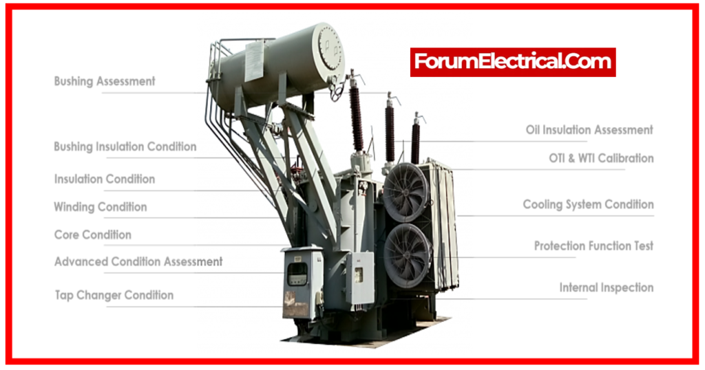
Electrical Test
An electrical test may comprise of all of the following:
- Insulation resistance at the core.
- Windproof insulating resistance.
- All taps exhibit wind resistance.
- Conduct a tan δ transformer bushing test.
- Conducted polarity & vector group tests.
- Test the turn ratio.
- Test the tap changer’s local and distant functionality.
- Test rotation and operation of fan groups 1 & 2 (every one transformer has two cooling fan groups).
- Conduct current transformer testing.
- Oil sample breakdown (BDV test) high voltage test.
Surge Arrester Test
Visual checks must involve the nameplate, terminal connections, earthing, and any other associated components as specified in the instruction manual.
Visual Check
Visually inspect the nameplate, connections, earthing, and all other associated things as specified in the instruction manual.
Electrical Test
An electrical test may include all of the following:
- Insulation resistance test
- Tan δ test
- Measure the leakage current.
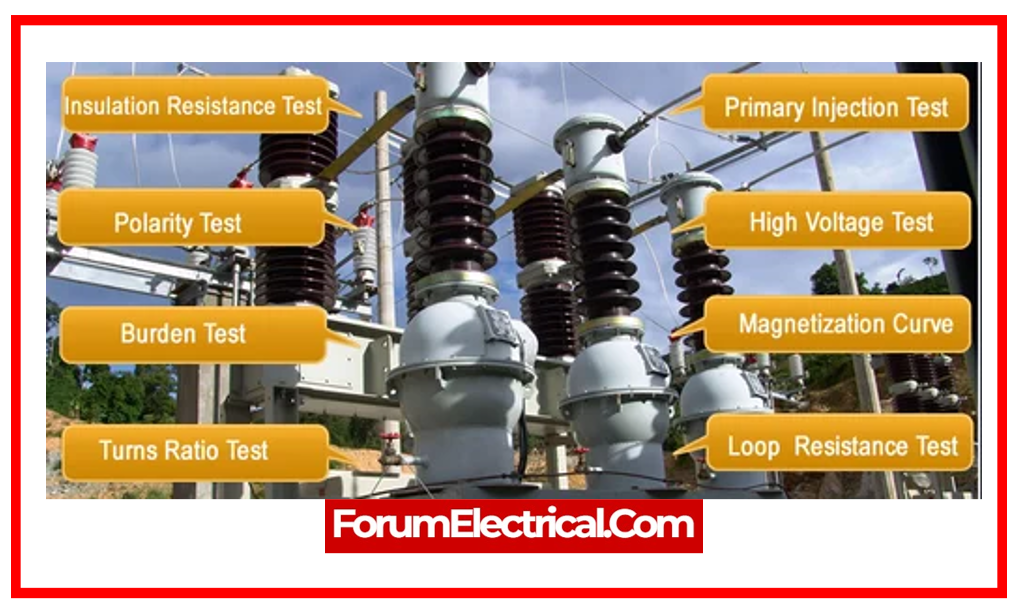
Current Transformer (CT) Commissioning Test
Visual Check
Visually inspect the CT for any damage, cracking, or oil leaks.
Electrical Commissioning Test
- An electrical test can entail any of the following:
- Insulation resistance test
- Winding resistance test
- Conduct a Polarity test
- Use principal injection for ratio testing
- Magnetizing current test
- Loop resistance burden test
- Ensure continuity of the secondary circuits
- Terminations and shortening linkages using main and secondary injection tests
- When the air insulated substation (or) gas insulated substation (GIS) commissioning tests, disconnect the current transformer (CT) connections to the relays and short the CT secondaries to perform the high voltage test
- Demagnetize the current transformer cores by connecting their secondaries to ground at the end of each test.
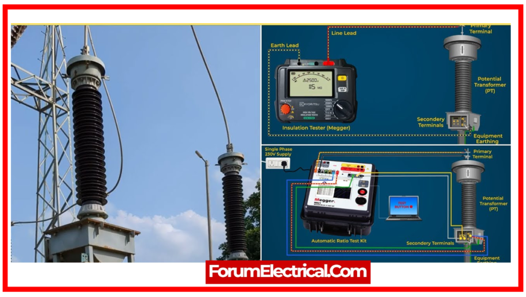
Voltage Transformer (VT) or Potential Transformer (PT) Commissioning Test
Visual Check
Visually inspect the potential transformer for any damage, cracking, or oil leaks.
Electrical Commissioning Test
An electrical test may include each of the following:
- Winding resistance test
- Insulation resistance test
- Ratio Test
- Conduct a Polarity test
- Check MCB trips using secondary injection in the voltage transfer secondary circuits
- Phasing test
- Loop resistance burden test
- Tan δ test.
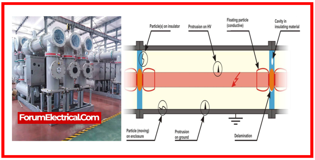
Gas-Insulated Switchgear (GIS) Commissioning Test
Visual Inspection & Mechanical Test
Checks should include nameplate information for all components:
- Circuit breaker (CB),
- Disconnect switch (DS),
- Earthing switch (ES),
- Current transformer (CT),
- Voltage transformer (VT),
- Enclosure earthing,
- Mechanical interlocks,
- Gas handling unit, and
- Dew point test for each gas compartment at the compartment’s rated gas pressure.
A gas leakage test at every joint should be performed with gas detectors (or) a plastic bag test surrounding joints.
Testing should involve the operation of gas density switch alarms, trip signals, and lockout functions, as well as CBs, DSs, ESs, and LCCs.
Electrical Test
An electrical test may include each of the following:
- Conduct insulation resistance tests for all wiring & cables.
- Conduct an interlocking circuit test.
- Resistance tests for busbar joints at 100 Amps DC.
- Earth resistance at 100 Amps DC.
- Check LCC functionality, comprising interlocking, bay control unit, alarms, and interface circuits with GIS and protection/control circuits.
- Conduct circuit breaker tests, timing (close & open), DS (close and open), including unique auxiliary connections for busbar protection, and examine the CB mechanism.
- VT/CT testing.
- Conduct heater checks in low-cost countries, particularly those with cold weather.
- GIS components, including CBs and DSs, are subjected to a one-minute-high voltage test with the VT disconnected & CT secondary circuit shorted in accordance with international standards.
High-Voltage Cable Commissioning Test
Visual Check
Checks should involve checking the tightness of connections with a torque wrench tool.
Electrical Test
An electrical test may include all of the following:
- Conducting a phase test.
- High-voltage test.
- Insulation resistance tests.
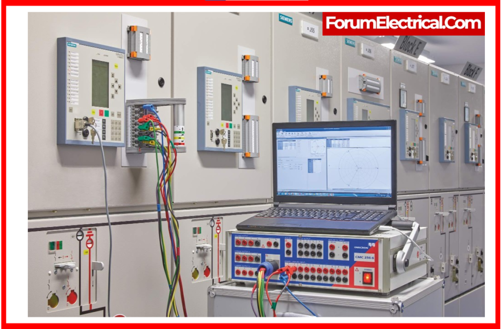
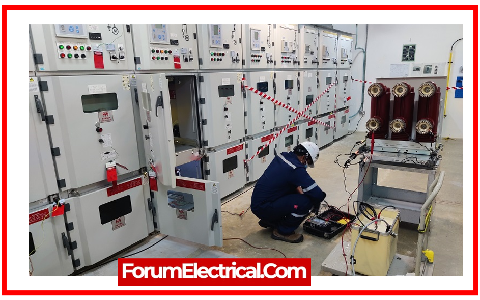
Protection & Control Panels Commissioning Test
Visual Check
Electrical Test
An electrical test may include each of the following:
- Test the auxiliary relays.
- Conduct secondary injection experiments.
- Primary injection tests.
- Run scheme function tests.
- Conduct on-load tests.
- Tripping tests.
- Testing the metering panels.
- Test the alarm and annunciators.
- Perform fault recorder panel checks.
- Conduct end-to-end tests for line differential protection & distance schemes.
- Testing the stability of transformer differential protection at 380 V.
- Tests on remote taps and charger panels.
- Bus transfer (ATS) system in 11kV switchgear.
- Test SCADA signals and alerts from station to the master station.
Final Energization Commissioning Procedures
Before energizing, these points must be confirmed:
- A transient overcurrent commissioning setting is applied to the bus coupler to speed up relay operation during initial energization.
- All circuits will be powered by the station’s bus coupler.
- Remove CT secondary shorting linkages.
- The final settings for all protective relays are being worked on.
- All PR (or) VT MCBs is closed, with no disproportionate alarms present.
- Engineers and technicians should not enter the switchgear area while energized.
- There is no earthing in primary circuits.
- After activating the new circuit, conduct a phasing test across the circuit VT secondaries & the existing standard circuit VT secondaries.
All of this should be completed prior to the loading of new circuit.
After the NCC gradually loads the circuit, the following steps should be taken:
- Verify the current values on each phase for the protective relays on each panel, including metering panels.
- Conduct directional tests on directional & distance relays using at least 10% to 30% of the load current, depending on whether they are electromechanical or digital.
AC Distribution Panel Commissioning Test
Visual Check
A visual inspection should involve tightening the bolts of low voltage AC busbars with a torque wrench tool.
Also, check the MCB & CB ratings against the drawings, as well as the panel earthing.
Electrical Test
An electrical test may include:
- Conduct insulation resistance tests.
- Check cables for proper phasing.
- Calibration of meters, including amperage and voltage meters.
- Checking auxiliary relays.
DC Distribution Panel Commissioning Test
Visual Check
This check should include the MCB and CB ratings as specified in the drawings, the tightness of busbar bolts using a torque wrench tool, and the panel earthing (proper cable cross-section) for the earthing.
Electrical Test
An electrical test might entail each of the following:
- Ensure insulation resistance for all busbars & internal wiring in panel.
- Check for polarity.
- Operating and tripping MCBs.
- Check the earth fault relay on the panel.
Battery Commissioning Test
Visual Check
A visual inspection should include checking the tightness of bolts with a torque wrench tool, looking for any earth on the battery’s positive and negative lines, checking the safety equipment in the battery room, ensuring the correct electrolyte specific gravity & liquid level, & checking the position and operation of the battery bank’s isolation switch.
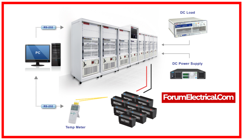
Electrical Test
An electrical test may include each of the following:
- Checking each cell’s voltage.
- Discharge test.
- Recharge test.
Battery System Start-Up and Commissioning Procedure
UPS and Battery System Commissioning Checklist
Battery Charger Commissioning Test
Visual Check
Verify that there are no damaged (or) disconnected wires within the panel.
Electrical Test
An electrical test can involve each of the following:
- Conduct insulation resistance tests for external cables.
- Verify quick and floating charge functioning throughout battery commissioning tests.
Testing References
References for evaluating & testing the power systems include:
ANSI C37.50: Low-Voltage AC Power Circuit Breakers utilized in enclosures.
IEEE 450: Recommended Practice for Maintaining, Testing, and Replacing vented lead acid batteries for the stationary applications
NFPA 70B: Recommended practices for Electrical Devices Maintenance
NFPA 110: Standard for Emergency & Standby Power Systems.
NFPA 111: Standard for the Stored Energy Emergency & Standby Power Systems.
Advantages of Commissioning Power Systems
- Electrical systems that fulfill the user’s operational needs.
- Reduced downtime from power outages due to utility loss and/or faults inside the power system
- Coordinated power systems that balance protection with reliability and fulfill the latest code requirements & standards for the critical facilities.
- Assurance that the power systems will function properly when required
- Knowledge of and expertise operating electrical equipment.
