
- What is an Electrical Fault?
- How to Detect & Locate Faults?
- What is Power System Failure?
- Open Circuit Fault
- Short Circuit Fault
- Symmetrical Faults
- Unsymmetrical Fault
- Causes of Different Types of Electrical Faults
- Effect of Different Types of Electrical Faults
- Fault Limit Devices
- What is Through Fault in Power System?
- Power System Fault Analysis
- 7 Steps to perform Power System Fault Analysis
What is an Electrical Fault?
An electrical fault is the divergence of voltages & currents from their nominal values or states. Under typical operating conditions, power system equipment (or) lines transmit regular voltages and currents, making the system operate more safely.
The fault in the power system is described as a flaw in the power system that causes the current to deviate from its intended path.
The failure causes an abnormal state, which diminishes insulation strength between conductors. The reduction in insulation causes significant damage to the system.
However, when a fault develops, abnormally large currents flow, causing damage to the equipment and devices.
Faults in power systems are mainly caused by
- Insulation failure,
- Flashover,
- Physical damage, or
- Human mistake.
Fault detection and analysis are required for selecting or designing appropriate
- Switchgear equipment,
- Electromechanical relays,
- Circuit breakers, and
- Other protection devices.
There are two basic forms of faults in the power system:
- Open Circuit Fault
- Short-circuit Fault.
These defects can be three-phase in form, involving all three phases symmetrically, or asymmetrical, with just one or two phases typically implicated.
Power system faults can arise as a result of a variety of natural disturbances such as lightning, high-speed winds, and earthquakes. It may also occur as a result of an accident, such as falling down a tree, a vehicle colliding with a supporting structure, an airplane crashing, and so on.
How to Detect & Locate Faults?
Transmission line faults are easy to identify because their condition is visible. Any tree that falls over a transmission line might destroy an electrical pole and the conductors underneath.
When a cable system circuit isn’t working, fault locating may be done. Terminal fault location methods use currents and voltages sensed at the cable ends, while tracer methods need cable screening.
Cable Tracing over the transmission line cable is faster when faults are located near the terminal.
Wire checking identifies electrical system faults. Time-domain reflectometers transmit a pulse down the wire and study the reflected signal to detect electrical wire faults in complicated wiring systems with buried wires.
Response galvanometers were used at fault cable ends to calculate fault currents in a prominent undersea telegraph cable. Cable faults are located using the
- Varley loop &
- Murray loop.
A power wire insulation failure cannot occur in low voltages. A high-voltage with high-energy pulse is applied to the cable for a thumper test. Listen to the discharge sound at the error can locate the malfunction.
If this test causes cable damage, it’s useful because the faulted area must be re-insulated anyway.
Feeders can expand faults to earth in high-resistance grounded distribution systems, yet the system keeps running. A ring-type current transformer combines all phase wires for the circuit and contains the faulted and energized feeder.
A fault to earth will show a net disturbed current. The grounding resistor helps identify the earth fault current between two values to beat it.
What is Power System Failure?
A power failure (also referred to as a power loss, power outage/power outrage, power cut, or blackout) is a temporary or permanent loss of electric power to a specific area. There are numerous causes of power outages in an electrical network.
Open Circuit Fault
The open circuit fault is primarily caused by the failure of one (or) two wires. The open circuit fault occurs in series with transmission line, hence the name “series fault.” These faults have an impact on the system’s reliability. The open circuit fault is classified as:
- Open Conductor Fault
- Two conductors Open Fault
- Three conductors Open Fault.
Causes of Open Circuit Fault
These breakdowns might be caused by a faulty circuit or a broken conductor in a single or several phases.
Effects of an Open Circuit Fault
- The electrical power grid operates irregularly.
- These faults can be a hazard to both animals and humans.
- When the voltage is raised over typical levels in some parts of the network, insulation fails and short circuit issues emerge.
- Even though these kinds of circuit faults may be tolerated for a longer period of time than short circuit faults, they must be disconnected in order to reduce the severe damage.

Short Circuit Fault
Short circuit faults are mostly caused by failures in the insulation between phase conductors and the ground.
An insulation failure can create a short-circuit path, triggering short-circuits conditions inside the circuit.
A short circuit is defined as an abnormal connection with extremely low impedance between two locations of differing potential, made by chance or on purpose.
These are the most prevalent defects that cause abnormally high current flow across transmission lines (or) equipment.
Short circuit defects, even if permitted to continue for a short period of time, cause extensive damage to the apparatus.
Short circuit faults are also referred to as shunt faults since these faults generally occur because of a failure in the insulation between phase conductors or between phase conductors and earth.
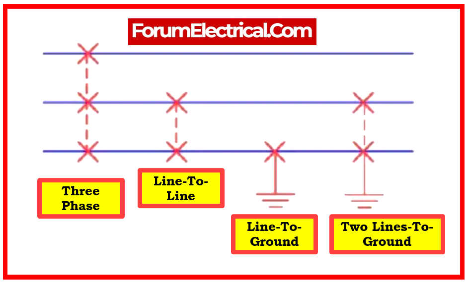
The various attainable short circuit fault occurrences include
- Three-Phases to Earth Fault,
- Three-Phases clear to the Earth Fault,
- One-Phase to Earth Fault,
- Phase Fault to Phase Fault,
- Two-Phase to Earth Fault,
- Phase to Phase Fault, and
- Single-Phase to Earth Fault.

The short-circuit fault is classified into
- Symmetrical Faults and
- Unsymmetrical Faults.
Short-circuit current calculations in electrical power systems are outlined in IEC 60909. These calculations are necessary for fault current analysis and protective device design.
Causes of Short Circuit Faults
- These faults may emerge due to internal or external influences.
- Internal impacts include transmission line failure, equipment damage, insulation aging, insulation corrosion within the generator, incorrect installation of electrical devices and transformers, and inappropriate design.
- These faults can arise as a result of outside effects on the equipment, insulation failure due to illumination surges, or mechanical damage caused by the public.
Effects of Short Circuit Faults
- Arcing faults may lead to fires and explosions in equipment like as transformers and circuit breakers.
- If the short circuit mistake persists, the flow of electricity may be significantly reduced or completely interrupted.
- System operating voltages can exceed or fall below their acceptability values, causing a negative impact on the service supplied by the power system.
- Because of irregular currents, the device heats up, reducing the life lifetime of its insulation.
Symmetrical Faults
These are extremely severe faults that occur infrequently in power systems.
Symmetrical faults involve all three phases. Such faults remain balanced even after they occur.
The majority of symmetrical faults occur at the generator terminals. The failure in the system could be caused by arc resistance between the conductors (or) decreased footing resistance.
Only 2-5 % of the system faults are symmetrical. If these faults occur, the system stays balanced, but the electrical power system component sustains severe damage.
This defect is simple to analyze, and it is typically done in stages. 3-phase fault analysis (or) information is essential for selecting set-phase relays, determining circuit breakers’ rupturing capacity, and rating protective switchgear.
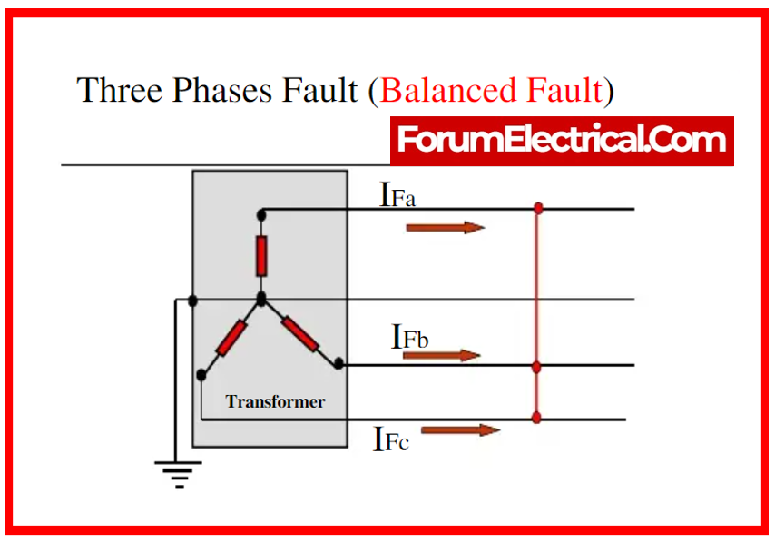
These are also known as balanced faults, and they are classified into two types:
- Line-to-Line to Ground (L-L-L-G) Fault and
- Line-to-Line Fault.
Line-to-Line to Ground (L-L-L-G) Fault
These types of faults are balanced, which implies the system stays balanced even after the fault has occurred. As a result, this L – L – L fault happens rarely, while being the most severe type of fault with the highest current. So, this current is utilized to compute the CB’s rating.
Line-to-Line Fault
The 3-phase L-G fault primarily impacts all three phases of the system. This problem mostly affects the system’s three phases and ground terminal. So, there is a 2-3% chance that the fault may occur.
Unsymmetrical Fault
The fault causes unsymmetrical current, which is defined as current that varies in magnitude and phase throughout the all 3 phases of the power system. It is also characterized as a fault with one or two phases, such as an L-G, L-L, or L-L-G fault. The asymmetry makes the system as unbalanced.
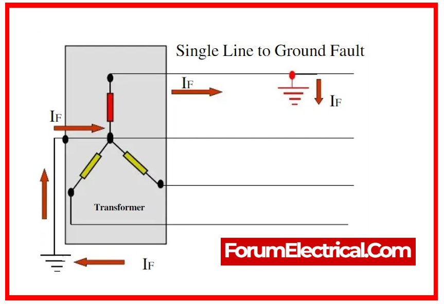
The most prevalent type of fault is the line-to-ground fault (L-G), that is responsible for 65-70 % of all breakdowns.
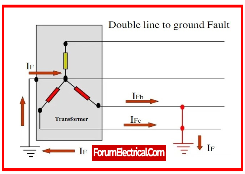
It causes conductor to get in touch with the earth, or ground. 15 to 20% of faults are double line to ground, which causes both conductors to make a connection with the ground.
Line-to-line faults occur when two conductors come into touch with each other, usually while lines are swinging due to winds, and constitute approximately 5- 10% of faults.
These are also known as imbalanced faults as their occurrence disrupts the system’s balance. The system is unbalanced because the impedance levels in each phase differ, causing unbalanced current to flow between the phases. These are more complex to evaluate and are carried out on a per-phase basis, much like three-phase balanced faults.
Unsymmetrical faults are categorized into three types.
- Single L-G (Line-to-Ground) Fault,
- Line-to-Line (L-L) Fault, and
- Double L-G (Line-to-Ground) Fault.
Single L-G (Line-to-Ground) Fault
This single L-G fault frequently occurs when a single conductor falls towards the ground terminal. So, the single L – G fault causes around 70 to 80% of all faults in the power system.
Line-to-Line (L-L) Fault
This L-L fault happens most frequently when two conductors are short-circuited, as well as when there is a strong wind. As a result of the heavy wind, the line conductors may move and come into contact with one another, resulting in a short circuit. As a result, around 15-20% of defects can arise.

Double L-G (Line-to-Ground) Fault
This type of fault occurs when two lines come into contact with each other via the earth. So, there is a 10% possibility of a fault.
Causes of Different Types of Electrical Faults
Weather Conditions
It includes lightning strikes, heavy rains, strong winds, salt deposition on the overhead lines & conductors, snow & ice accumulation on the transmission lines, and so on. These climatic conditions disrupt the power supply & damage electrical infrastructure.
Human Errors
Human mistake can also create electrical failures, such as selecting an incorrect rating for equipment or devices, ignoring metallic (or) electrical conducting sections after servicing (or) maintenance, switching the circuit when it is being serviced, and so on.
Equipment Failures
Short circuits are caused by a variety of electrical equipment, including
- Generators,
- Motors,
- Transformers,
- Reactors,
- Switching devices, and so on,
due to malfunctioning, aging, cable insulation failure, and winding. These failures cause significant current to pass through the devices (or) equipment, severely damaging them.
Smoke from Fires
Ionization of air caused by smoke particles surrounding overhead wires results in a spark across the lines (or) between conductors and the insulator. Insulators decrease in insulating capacity as a result of the high voltages during this flashover.

IEEE 1584 – A Guide for Calculating Arc-Flash Hazards This standard establishes standards for evaluating arc-flash dangers in electrical systems, including techniques for determining incident energy & arc flash boundary.
Effect of Different Types of Electrical Faults
Over Current Flow
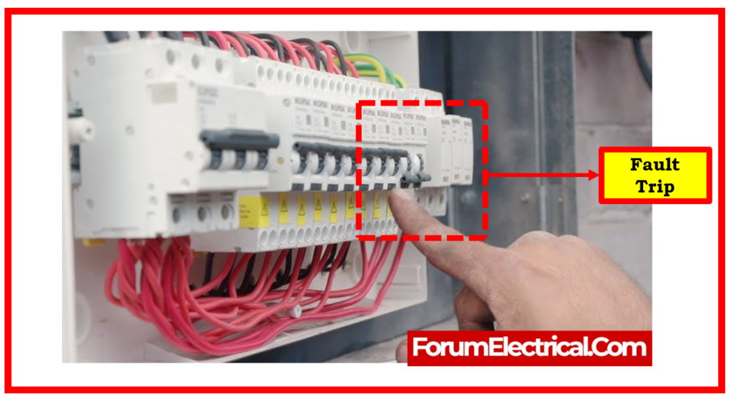
When a failure occurs, it generates an extremely low impedance path for current to flow. As a result, a large amount of current is pulled from the supply, leading relays to trip and destroying insulation and equipment components.
Loss of Equipment
Heavy current owing to short circuit faults causes the components to entirely burn out, resulting in poor operation of the equipment or device. Heavy fire can cause full burnout of the devices.
Danger to Operating Persons
Individuals may also be shocked when a fault occurs. The strength of the shock is determined by the current & voltage at the fault point, and it may even cause death.
Disturbs Interconnected Active Circuits
Faults affect not just the site where they occur, but also the active that are interconnected circuits that connect to the damaged line.
Fault Limit Devices
It is possible to reduce factors such as human mistake, yet not environmental changes.
Fault clearance is a significant responsibility in the power system network. If we can disrupt (or) break the circuit once a fault occurs, we can prevent significant damage to the equipment and property. Fuse, circuit breakers, and relays are some of the fault-limiting devices.
Fuse
It serves as the principal protective device. It is a small wire wrapped in a shell or glass that links two metal components.
When there is an excessive amount of current in the circuit, the wire melts. The type of fuse is determined by the voltage that determines when it will work. After a blowout, the wire must be replaced manually.
Circuit Breaker
It creates the circuit normally and breaks it when abnormal situations occur. It automatically trips the circuit if a fault occurs. It may include electromechanical circuit breakers (such as vacuum/oil circuit breakers) (or) ultrafast electronic circuit breakers.
Relay
It is a conditional functioning switch. It is made up of a magnetic coil and standard open & closed contacts. Fault incidence increases the current, that energizes the relay coil, causing the contacts to operate and interrupting the flow of current. There are several varieties of protective relays, including impedance relays and mho relays.
Lighting Power Protection Devices
These include lightning arrestors and grounding devices, which protect the system from lightning and surge voltages.

What is Through Fault in Power System?
The through fault arises outside of the protection zone. In terms of external faults that arise outside of the equipment’s protective zone are referred to as through faults.
Power System Fault Analysis
Power system fault analysis is the process of detecting and diagnosing defects or faults in an electrical power system. These faults can vary from short circuits to equipment breakdowns, with serious consequences for system reliability & safety.
IEEE 141 is the standard provides rules for fault analysis and protection coordination, as well as advice for the design & installation of electrical power distribution systems in the industrial plants.
The analysis typically involves acquiring data, such as voltage & current measurements, & then applying various methodologies to determine the position and nature of the problem. This could include mathematical modeling, simulation, & specialized testing processes.
Engineers can utilize fault analysis to identify the source of interruptions, analyze their impact on the system, & implement ways to limit risks and quickly restore normal operation.
7 Steps to perform Power System Fault Analysis
Here, we will detail the seven steps necessary to perform a fault analysis in a power system for a specific failure.
1). Converting to Base Values: Change the system to a per-unit system with the same base value.
2). Type of Fault: Determine the sort of fault being examined.
3). Constructing Sequence Networks: From the system converted in step 1, draw sequence networks on all of the positive, negative, and zero sequence networks.
4). Create a Faulted Sequence Network Diagram: To create a faulted sequence network diagram, change and interconnect the un-faulted sequence networks based on the type of fault.
5). Hand Calculation: During a faulty condition, manually compute the sequence currents & voltages.
6). Convert the per unit value into current & Voltage value: Convert the per unit numbers calculated in the step 5 into 3 phase current & voltage quantities which may be used and understood intuitively.
7). Transformer LV side Fault Calculation: Calculating the fault which occurs on the transformer’s low voltage side.