
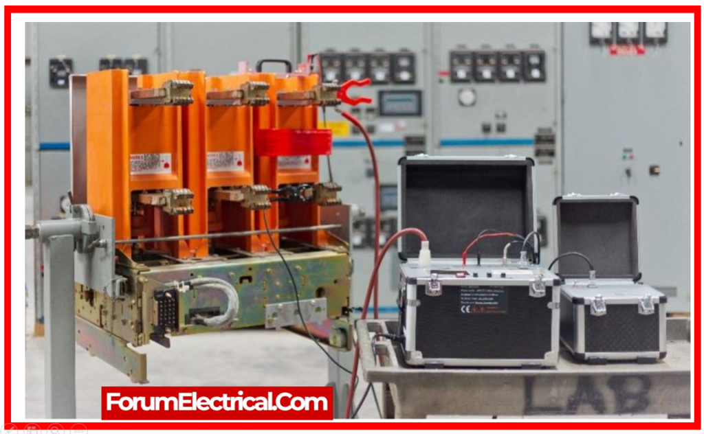
Circuit breaker testing is used to ensure that each switching system operates properly and that the complete tripping structure is programmed correctly.
Circuit breaker testing is required to assure the safe and reliable operation of this critical component in the power asset chain. Circuit breakers serve three basic functions:
They should carry the current as efficiently as possible when closed.
When open, they must provide as much insulation between the contacts as possible.
Trip Profiling, which is another term for Circuit Breaker Testing,
In case of a malfunction, it’s necessary to disconnect the fault current as soon and reliably as feasible to protect all subsequent equipment.
Circuit breaker testing becomes more difficult than evaluating other electrical components such as transformers due to the higher short circuit current.
Why is it important to test Circuit Breakers?
A circuit breaker may remain unused for years, but if a failure arises, it must gradually remove fault currents of hundreds of kiloamps within a few milliseconds.
Major problems on circuit breakers include inaccurate action, short circuits in the coils, and damage to mechanical connections (or) insulation material. Circuit breakers must therefore be inspected on a regular basis and with care.
Circuit breakers serve a vital function in protecting expensive equipment from damage caused by faults, such as connecting and disconnecting electrical power in a reliable manner; this requires proving their reliability with on-site tests during installation and regular maintenance tests throughout its lifetime to avoid costly failures and problems that might threaten the substation’s safety.
Testing the operation of the circuit breakers on a regular basis is thus an important and cost-effective component of any maintenance schedule.
Circuit breaker testing focuses primarily on acquiring motion and time measurements from the components.
However, the test methods have transformed circuit breaker testing.
Conducting the tests without using the station battery significantly improves safety during the testing process.
Preventative Maintenance, Inspection, & Testing
Circuit breakers require preventative maintenance depending on their operational conditions.
Primary tests of CBs (circuit breakers) will check for particle matter compromising the CB’s inner workings. To clean away accumulated dust, toggle the “Off” and “On” switch on the breaker.
Type Tests of the Circuit Breaker
Type tests are conducted to demonstrate abilities and ensure that the circuit breaker’s rated characteristics are correct. Such tests take place in a well-equipped testing laboratory.
Mechanical Test
This is a mechanical ability test that involves repeatedly opening and closing the breaker. A circuit breaker must close & open at the right speed, do its assigned purpose, and perform without failure.
Thermal Test
Thermal tests are performed to determine the thermal energy of the circuit breakers. The breaker under test experiences steady-state temperature increases as rated current flows through its pole in a rated condition. The temperature rise for the rated current cannot exceed 40° for currents less than 800A and 50° for 800A and higher.
Dielectric Test
These tests are used to determine power frequency and impulsive voltage withstand capabilities. Power frequency tests are performed on a new circuit breaker and the test voltage varies with the circuit breaker’s rated voltage. In impulse testing, an impulse voltage of a specific value is applied to the breaker. Outdoor circuits are tested both dry and wet.
Short-Circuit Test
In short-circuit test labs, circuit breakers are exposed to sudden short-circuits, and oscillograms are recorded to determine the behavior of the circuit breakers at the point of switching in, at contact breaking, and after arc extinction.
The oscillograms are analyzed in detail, with a focus on generating and breaking currents, as well as symmetrical & asymmetrical restriking voltages, & switchgear is occasionally tested under rated conditions.
IEEE C37.09 standard specifies procedures for the testing high-voltage circuit breakers utilized in power systems. It includes many types of tests such as mechanical, electrical, and thermal tests.
Routine Tests of the Circuit Breaker
Routine testing is performed in accordance with the standards of the Indian Engineering Service & Indian Standards. These testing are carried out on the manufacturer’s premises.
Routine checks indicate that the circuit breaker is functioning properly. Routine testing does not always include complex equipment in order to make sure that a circuit breaker is operational.
Routine maintenance and ensuring that circuit breaker performance corresponds with the manufacturer’s calibration curves are two guidelines & recommendations for these tests.
It is essential that these tests are carried out under stable conditions and at appropriate temperatures to ensure that the data is consistent.
Several of the tests are given below:
1). Power Frequency Overvoltage Withstand Test
2). Circuit Breaker Trip Test
3). Insulation Resistance Test
4). Connection Test
5). Contact Resistance Test
6). Overload Tripping Test
7). Instant Magnetic Tripping
8). Dielectric Test for Auxiliary and Control Circuits
9). Tightness Test
10). Visual Checks
1). Power Frequency Overvoltage Withstand Test
The power system might encounter various transient power over voltage conditions as a result of a
- Sudden loss of load from the system,
- Incorrect operation of an online tap changer,
- Insufficient shunt compensation in the system.
A power frequency over voltage withstand test of a circuit breaker is performed to ensure that the insulation strength of the main circuit is sufficient to tolerate such abnormal over voltage situations in the system.
The circuit breaker must additionally be built to tolerate overvoltage’s caused by lightning & switching impulses.
A circuit breaker, like other expensive technical equipment, is designed to withstand a wide range of unexpected events while remaining cost-effective.
A circuit breaker must undergo and pass many dielectric tests to ensure its capacity to withstand all types of overvoltage circumstances while maintaining cost-effectiveness.
2). Circuit Breaker Trip Test
The current absorbed by the trip coil at the operation of the circuit breaker can be used to detect whether mechanical or electrical problems exist. In many cases, such faults can be recognized to help identify the root cause. Monitoring the voltage of the tripping supply during operation is an option for detecting difficulties with tripping batteries.
3). Insulation Resistance Test
For each breaker resistance testing, load & line conductors should be separated. If not removed, the test results will include the properties of the attached circuit.
Resistance testing is important for ensuring that the insulating material that makes up the molded case breakers is functioning properly. To measure insulating resistance, a megger is employed.
A megger instrument distributes a known DC voltage to a wire for a set amount of time to measure the resistance within the insulation of that wire (or) winding. It is essential to use voltage because resistance measured with an ohmmeter (Ω) can vary when there is no indication of potential differences.
It must also be noticed that if apply a voltage that is too high for the insulation to withstand, that risk damaging it.
4). Connection Test
Connection testing is necessary to ensure that a proper electrical connection is available & to detect signs of overheating as indicated by a color difference. It is essential that electrical connections to the CB are properly established to avoid and decrease overheating.
5). Contact Resistance Test
After prolonged use, normal wear & tear of the CB’s contacts occurs. Quantifying the resistance across each pole of the circuit breaker is a simple way to detect signs of weakening.
Excessive millivolt reductions across the breaker indicate abnormal conditions within the CB, such as
- Contact erosion and
- Contamination.
The contact resistance test serves as essential for determining whether circuit breaker is still functional.
6). Overload Tripping Test
Overload tripping components of CBs can be tested by entering 300% of breaker rating into every pole of circuit breaker to ensure that it opens immediately.
The purpose is to ensure that circuit breaker operates or not. Refer to NETA standards to determine permissible trip times for the overload tripping test.
When attempting to determine tripping characteristics, it is preferable to refer the manufacturer’s manual.
7). Instant Magnetic Tripping
In normal tests, it is more important to determine whether the magnetic feature is functioning and will trip the circuit breaker than to determine the exact value that determines whether the instantaneous magnetic characteristic functions.
8). Dielectric Test for Auxiliary and Control Circuits
There may also be unexpected overvoltage conditions in the auxiliary & control supply circuits.
As a result, the auxiliary & control circuits of breakers must also pass a short-duration power frequency voltage withstand test.
The test voltage of 2000 V is administered for one minute.
The insulation of the auxiliary and control circuits should pass this test, and no destructive discharge should occur during the test.
ANSI/IEEE C37.50 standard specifies test procedures & acceptance standards for circuit breakers rated at more than 1000 volts. It involves tests to determine dielectric withstand, interrupting capacity, & insulation resistance.
9). Tightness Test
This test is performed on primarily gas-insulated switchgear. This test measures the leakage rate.
This test maintains the switchgear’s desired longevity. All of the jointing points in the gas-containing paths are air-tightly covered with thin sheets of polythene (preferably transparent) for over 8 hours, and the gas density inside these covers is measured by inserting a gas detector’s gas detecting port through a hole created on the covers.
The measurement is conducted in ppm units and must be within the prescribed limits. The maximum gas leakage level of 3 ppm/8 hours is used as a standard.
10). Visual Checks
The circuit breaker needs to be visually inspected for terminology data on the templates, suitable identifying marks on any auxiliary equipment, paint color and quality, corrosion on metallic surfaces, and so on.
General Procedures for the Routine Field Testing
To ensure that a CB is operational, routine field testing does not require the use of complex equipment.
Routine maintenance and ensuring that circuit breaker performance aligns with the manufacturer’s calibration curves are guidelines & recommendations for these tests. To avoid data variations, these tests must be performed under controlled settings at ambient temperature.
How are Circuit Breakers Tested?
Different circuit breaker test equipment is used to inspect the operation & condition of circuit breakers in power systems.
Trying to test a circuit breaker requires a variety of test methodologies and testers.
This will explain how to test a circuit breaker using various testing instruments to ensure that the equipment functions properly under a variety of conditions or operating types.
1). Testing using the Circuit Breaker Analyzer
2). Testing using a Micro-Ohmmeter
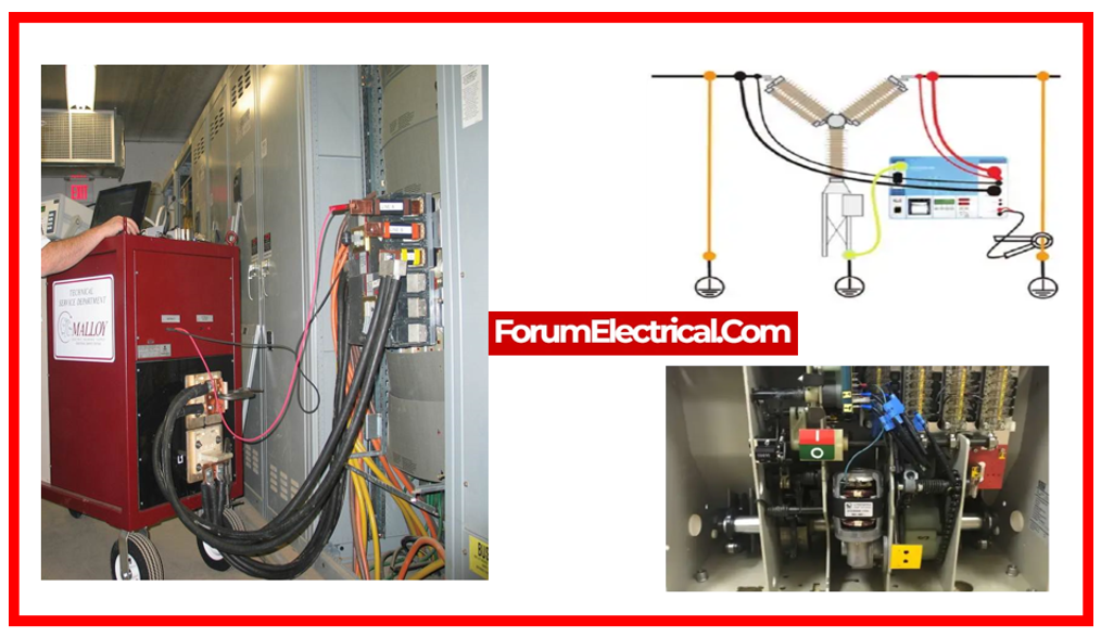
3). Testing using a high current Primary Injection Tester
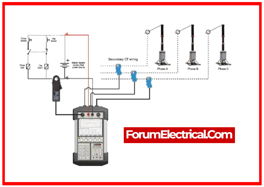
1). Testing using the Circuit Breaker Analyzer
Timing tests of the various open and shut operations of the breaker are an effective method to evaluate a circuit breaker because they analyze not only the trip times but additionally the important synchronism of poles in every operation.
This defines how to test a circuit breaker using various simulations of its operation, that can be directly commanded from the circuit breaker analyzer (or) initiated by an external signal, and includes checking the opening or closing time of each pole in single (or) combined operations, as well as checking for differences between poles (or) mismatch time, which can lead to a dangerous lack of synchronization.
How to test a circuit breaker with the circuit breaker analyzer is also determined by the type of possible problems to be confirmed, that leads to checking other features such as possible bouncing, proper performance of the pre-insertion resistances, coil condition, and mechanical analysis via contact travel speed and acceleration data using the appropriate transducers.
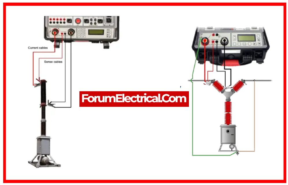
2). Testing using a Micro-Ohmmeter
Circuit breakers often carry a large amount of current. Greater contact resistance results in higher losses, lower current carrying capability, & threatening hot spots in the breaker, therefore resistance testing with the micro-ohmmeters is another technique to test a circuit breaker for finding and avoiding potential problems.
To test a circuit breaker using a micro-ohmmeter, consistent measurements & a wide injection range with the high power are required, which allows for longer test leads, less connection issues, and more precise measurements.
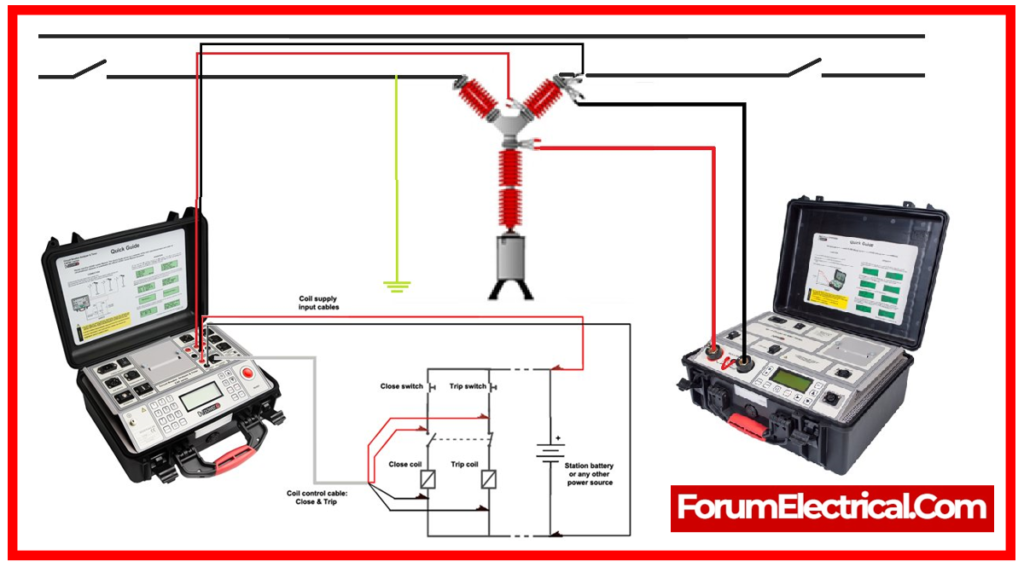
3). Testing using a high current Primary Injection Tester
The tripping time characteristics of Low Voltage (LV) and molded-case circuit breakers are analyzed using high current injection to ensure overall operation.
How to test a circuit breaker of this type is determined by its maximum rated current, trip protection settings, and inverse curve types, which define the overload & short-circuit trip pickup levels & time delays; all of these features must be checked with an appropriate primary injection test set capable of simulating the required high current faults and capturing the breaker’s response.
A system that can be simply improved in power capacity allows how to evaluate a circuit breaker in different possible situations & different range of breakers.
Advantages of Circuit Breaker Testing
- Quick and simple to execute on-site.
- Circuits may be tested either loaded or unloaded.
- Tests the performance of the entire tripping cycle
- Tests overall timing of the tripping system.
- Identifies the necessity for maintenance.
- Part of a complete diagnostic maintenance program.
- Find early signals of potential difficulties.
- Avoid complications besides picking up components.
- Create a test record report (or) database for trending.
- Pick out the unwanted conducting materials.
