
- What do you mean by the Inspection of Cables?
- Electrical Cable Types
- International Reference Standards
- Inspection Types
- 1). Basic Inspection
- 2). Visual and Mechanical Inspection
- 3). Routine Test
- 4). Sample Test
- 5). Type Test
- 6). Non-Electrical Type Test
- Electrical Inspection after Installation
- 1). AC Withstanding Voltage Test
- 2). DC Withstanding Voltage Test (ICEA only)
- 3). Power Cable Inspection: Insulation Resistance Test
- 4). Power Cable Inspection: Discharge Test
A cable is an assembly made up of two or more wires that are joined, twisted, or braided together and run side by side. Stranding electrical cables can increase their flexibility. This method creates larger, more flexible wires by twisting or braiding smaller, individual wires together, making them more flexible than solid wires of the same size. The most flexibility is added by bunching tiny wires before concentric stranding. A cable may contain bare copper wires.
What do you mean by the Inspection of Cables?
The major maintenance procedures for cable systems include visual inspection of cable installations, manholes, conduit, & other components, as well as electrical maintenance testing. Energized installations can be visually inspected.
Electrical Cable Types
There are 3 types of electrical cables based on voltage
1). Low Voltage (LV) Cable
2). Medium Voltage (MV) Cable
3). High Voltage (HV) Cable
International Reference Standards
| IEC 60332 | Fire-tested electric & optical fiber cables. |
| IEC 60502-1 | Power cables and accessories with extruded insulation for rated voltages ranging from 1 kV (Um = 1.2 kV) to 30 kV (Um = 36 kV). Part 1: Cables for rated voltages of 1 kV (Um = 1.2 kV) and 3 kV (Um = 3.6 kV). |
| IEC 60228 | Conductors of the insulated cable |
| BS 5467 | Thermosetting insulated electric cables, armored cables for voltages of 600/1000 V and 1900/3300V |
| IEC 60227 | Polyvinyl chloride-insulated cables with rated voltages up to and including 450/750 V |
| IEC 60245 | Rubber-insulated cables with rated voltages up to & including 450/750 V. |
| IEC 60811 | Common test techniques for insulating & sheathing materials of optical and electrical cables |
Inspection Types
Thorough electrical cable inspections are essential for ensuring safety, dependability, and compliance with guidelines. Here’s a general inspection t technique types for inspecting electrical cables:
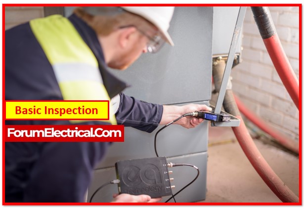
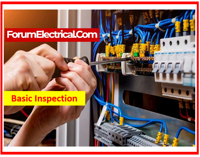
1). Basic Inspection
- Check to see if the model fulfils the specifications.
- Check that the cable logos are accurate (for example, the direction of the connector or the sides of the earphone).
- Check the cable for any breakages.
- Check to see if the cable & connector are well connected.
- Check if the metal on the connector has rusted.
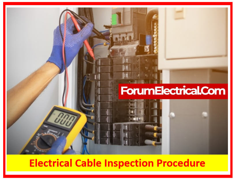
- Use a multimeter to determine whether the cable has good conductivity.
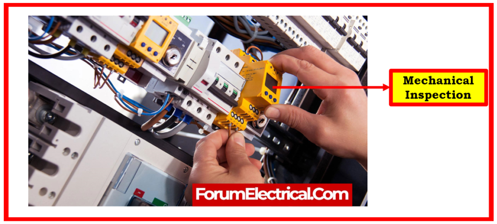
2). Visual and Mechanical Inspection
- Compare cable data to drawings and specs.
- Inspect exposed cables for the physical damage.
- To inspect bolted electrical connections for high resistance, use one of the following methods:
- Use a low-resistance ohmmeter.
- Check the tightness of exposed bolted electrical connections using a calibrated torque wrench.
- Perform a thermographic survey.
- Inspect compression-applied connections for proper cable alignment and indentation.
- Inspect the shield grounding, cable support, & termination.
- Ensure that visible cable bends meet (or) exceed the ICEA and/or manufacturer’s minimum permissible bending radius.
- Inspect the fireproofing in the common cable places.
- If cables are terminated via window-type current transformers, ensure that neutral & ground conductors are properly arranged and shields are properly terminated so that protective devices can operate.
- Inspect for proper identification & arrangement.
- Examine the jacket & insulation condition.
3). Routine Test
- Conductor electrical resistance measurement.
- Measure resistance on all cable lengths submitted for normal testing, including any concentric conductors.
- Use IEC 60228 formulas and factors to adjust resistance measurements to 20°C and 1 km length.
- For single and multicore cables with individual screening, apply a test voltage for 5 minutes between the conductor & metallic screen.
- Immerse single-core unscreened cables in room temperature water for 1 hour, then apply a test voltage for 5 minutes between the conductor and water.
Obtain the test voltage.
| Rated voltage kV | 0.6 | 1.8 |
| Test voltage kV | 3.5 | 6.5 |
4). Sample Test
Conductor Inspection:
- Insulation and sheath thickness measurements.
- Measure overall conductor diameter. –
- Choose one length from each manufacture series of the same kind & nominal cross-section of cable, up to a maximum of 10% of the contract lengths.
Check Dimensions:
- Measure the thickness of the lead sheath, bedding sheath, and armour wires.
- Measure the entire diameter.
Conduct hot set tests for EPR, HEPR, & XLPE insulations & elastomeric sheaths.
5). Type Test
- Measure insulation resistance at ambient temperatures.
- Measure insulation resistance at the maximum conductor temperature during normal operation.
- Test voltage for 4 hours.
- Before testing, submerge the cable cores in water at room temperature for at least 1 hour.
- A power frequency voltage must be gradually provided & maintained continuously for 4 hours between each conductor and the water.
Remember: Cables with a rated voltage of 1.8/3 (3,6) kV must also undergo an impulse test on then additional sample of the completed cable ranging in length from 10 to 15 meters. The tests will be limited to not over three cores.
6). Non-Electrical Type Test
- Measure insulation thickness
- Measure non-metallic sheath thickness (which includes extruded separation sheaths but not inner coverings)
- Determine insulation mechanical characteristics before and after ageing.
- Determine non-metallic sheath mechanical properties before and after ageing.
- Conduct additional ageing tests on completed cables.
- Loss of mass test for ST2 PVC sheaths
- High temperature pressure test for insulations and non-metallic sheaths
- Low temperature testing for PVC insulation and sheaths, including halogen-free sheaths.
- Heat shock test for PVC insulation and sheaths
- Ozone resistance test for EPR along with HEPR insulations
- Hot set test for EPR, HEPR, and XLPE insulations & elastomeric sheaths
- Oil immersion test for elastomeric sheaths
- Water absorption test on insulation
- Fire tests
- Measuring of carbon black concentration in black PE sheaths.
- XLPE insulation shrinkage test
- Special bending test
- HEPR insulation hardness determination
- HEPR insulation elastic modulus determination
- PE insulation shrinkage test for sheaths.
- Additional mechanical tests for halogen-free sheaths.
Electrical Inspection after Installation
1). AC Withstanding Voltage Test
The test voltage is conducted between the conductor(s) and the metallic shield, armour, or water. The total duration is 5 minutes, and the assessment will be considered satisfactory if it can sustain the specified voltage.
2). DC Withstanding Voltage Test (ICEA only)
All cables rated 5001 volts & higher are checked using the DC withstand voltage test & can be considered acceptable if sustain specified test voltage.
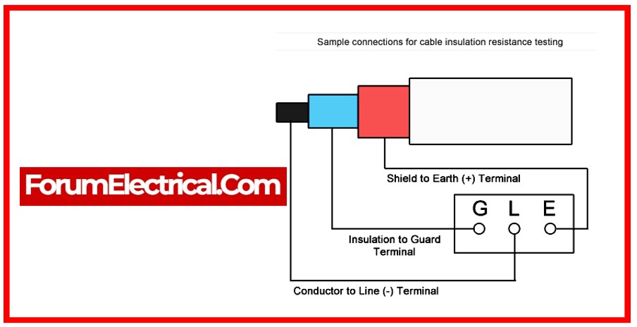
3). Power Cable Inspection: Insulation Resistance Test
The insulation resistance test is performed after the finished cable AC voltage test (or) before any DC voltage test & is witnessed by a third-party inspector.
The insulating resistance is measured for one minute, and the resultant value is acceptable if it exceeds the stated value in the requirement.
4). Power Cable Inspection: Discharge Test
The partial discharge test is performed prior to the AC voltage test, in accordance with the code and standard. AC test voltage is connected between conductor & the metallic component of the insulation shield.
If the presence of a discharge is not visible after raising the voltage to a value 20% higher than the prescribed minimum extinction value, the cable is regarded to meet the standards.