 Panel Testing Procedure")
- Purpose of Tests
- Reference Document
- Scope
- Terminology
- Test Equipment
- Equipment under Test
- 1). Preliminary Checks
- 2). Electrical Checks
- 3). AC Distribution Circuit Breaker (DCB) Test & Inspection
- 4). Electrical Testing of the Distribution Board
- 5). Energizing
- 6). Putting into Service
- Recording of Inspection & Test Results
Alternating current (AC) panel meters need regular maintenance to ensure linearity, hysteresis, and accuracy.
Purpose of Tests
These tests comprise inspection and testing of the main AC distribution board after installation and before energization.
This protocol establishes a safe, standardized strategy for the initial inspection, checkout, pre-commissioning testing, and data documenting of 400 V LV switchgear. Using various testing equipment can result in distinctly different steps.
Reference Document
- Single-Line Diagram
- Schematic Diagram
- Equipment Drawings
Scope
All working locations.
Terminology
Not Applicable
Test Equipment
- Digital Multimeter
- Milliohmmeter for continuous measurement.
- Megohmmeter (1000V DC)
- AC test set power supply and variable transformer for injection.
- Phase Sequence Tester
Equipment under Test
All distribution boards that receive a rated AC voltage of less than 1kV.
1). Preliminary Checks
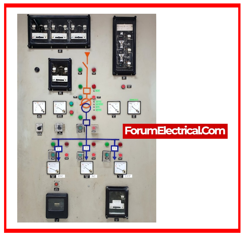
- Ensure all distribution board components (e.g., type, ratings, ground fault sensor, voltage monitoring relays, ammeters, voltmeters, circuit breakers) are properly installed and in accordance with the necessary designs.
- Ensure distribution board components are properly marked.
- Before working on the system, ensure no contact with electrified equipment is possible.
- Verify the primary bus bar & auxiliary circuits (monitoring, control, alarm, & fault) for continuity.
- Verify the grounding bus bar’s continuity & connection to the primary earthing system.
- Ensure panel hinged doors have been attached to the frame with earthing braids.
- Check door locks for proper operation.
- Ensure connections are tight and conform to reference drawings.
- Open all incomers & load circuit breakers.
- Ensure connections are tight and conform to reference drawings.
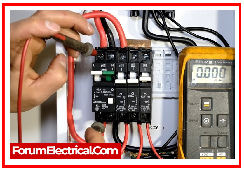
2). Electrical Checks
Continuity Test (Between each Metal parts & the Ground)
It is normally recommended that you use a milliohmmeter to evaluate continuity during this test.
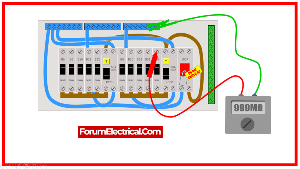
Distribution Board Insulation Resistance (IR) Tests
- It is suggested that these tests be performed before connecting to ensure that all isolating devices are closed.
- If the cables already have been connected, open the isolating devices prior to doing any tests. The downstream circuit will undergo power cable tests.
- Disconnect both the ground sensing device & the control cords.
- Utilizing a 1000 V DC megohmmeter (Megger), measure insulation resistance (IR value) after one minute of electrification.
- Connect each phase, together with the other two and neutral, to ground.
- Neutral & 3 phases, including ground.
- Utilizing a 500 V DC megohmmeter (Megger), measure the insulation resistance (IR value) after one minute of electrification between:
- Auxiliary circuit & ground.
- Reconnect the cables following testing.
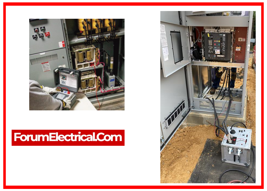
3). AC Distribution Circuit Breaker (DCB) Test & Inspection
Conformity Checks
Examine the circuit breakers for their presence and compliance with the reference drawings (type, thermal rating, magnetic rating, and label).
Mechanical Tests
- Check for proper racking in for the withdrawal circuit breaker, then check:
- A circuit breaker cannot be racked in a closed position.
- A circuit breaker cannot be closed if not properly racked in
- A circuit breaker cannot be racked out in the closed position.
- Check the closing & opening (or) tripping operation at zero load by:
- Manual actuation.
- Press the test pushbutton if applicable.
- Magnetic protection causes circuit breakers to trigger on short circuits.
- The tripping value must be modified but not verified via supplying power.
- Thermal protection triggers circuit breaker tripping at overloads.
- The tripping value must be modified but not verified via supplying power.
- Check the panel’s terminal blocks for correct circuit breaker position and alarm conditions.
4). Electrical Testing of the Distribution Board
Measurement & Protection Circuits Tests
Indicators
- Use a test set power supply to verify the values displayed on the indicators.
- If there are any associated converters, check the indications at the respective output terminal block.
Under (or) Overvoltage Protection
Check the relay operation utilizing a test set power supply and set it to the required rating.
The protection information reports must be verified up to the distribution board’s output terminal block.
5). Energizing
- Attach the incoming cables from the auxiliary transformer (or) main distribution board.
- Check for the presence of mechanical guards that prevent inadvertent contact with the live parts.
- Open all of the outgoing disconnection devices.
- Supply the distribution board through the incomer and verify voltage and proper phasing upstream of all the disconnecting devices, indicators, and protection.
- Verify the distribution board alarm information and return it to the output terminal blocks.
Automatic Transfer Switches
- Check the mechanical and/or electrical interlocks.
- Check for accurate phasing.
- With both accessible supplies, confirm the functional checks by the existence of voltage, loss of supply, and restoration of the supply in manual & automatic modes.
6). Putting into Service
- The two incoming supplies are ready on the LVAC (Low Voltage Alternating Current) distribution board.
- Check that all relevant protective & signalling devices are operational.
- Voltage measurement, phase sequence check, and voltmeter reading must be performed for each bus bar.
- Close all the outgoing circuit breakers as needed after testing the associated low voltage power wires and their phasing.
Recording of Inspection & Test Results
The results of the checks & measurements obtained during the field test must be recorded.

 Panel Testing Procedure describes how to test AC electrical panels for safety and functionality. This process examines AC panel reliability and electrical standards by measuring voltage, insulation resistance, and continuity. Technicians can reduce hazards and optimize electrical system performance by using this testing methodology to find any faults.)