 in Power Systems?")
The purpose of short circuit current in power systems method statement is to explain the engineering methods that is used to reduce short circuit current levels in electrical power systems.
- Scope
- Engineering Methods to Reduce Short Circuit Current
- Method-1: Increasing Cable Length (Applicable for LV Systems)
- Method-2: Installing a 1:1 Ratio Transformer
- Method-3: Installation of Current Limiting Reactor (CLR) – MV Systems
- Method-4: Installation of IS Limiter
- Method-5: Network Splitting (Bus Sectionalizing)
- Practical Application
- Summary
High fault current levels can exceed the switchgear interrupting capacity leading to
1). Equipment damage,
2). Fire hazards and
3). System shutdown.
This procedure helps to provides practical solutions to control and mitigate excessive the fault current in low voltage (LV) and medium voltage (MV) power systems.
Scope
This method statement applies to:
- Industrial power distribution systems,
- Utility substations,
- Power plants with internal generation (DG / generators),
- LV and MV electrical networks.
It is particularly relevant when:
- System capacity increases,
- Additional generators are installed,
- Network configuration changes,
- Fault level exceeds breaker interrupting rating.
Engineering Methods to Reduce Short Circuit Current
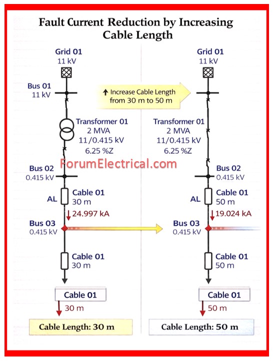
Method-1: Increasing Cable Length (Applicable for LV Systems)
Increasing the cable length between the source and load bus will increases the system impedance which reduces the short circuit current.
Principle
Longer cable creates higher impedance which lowers fault current.
Example
| Parameter | Value |
|---|---|
| Cable Length | 30 m |
| Fault Current at Bus | 24.997 kA |
| Breaker Rating | 20 kA |
Since the fault current exceeds the breaker capacity, the cable length is increased.
| Parameter | Value |
|---|---|
| New Cable Length | 50 m |
| Reduced Fault Current | 19.024 kA |
Advantages
- It is a simple engineering solution.
- No additional equipment needed.
Limitations
- Not always practical because of space constraints.
- May increase the voltage drop.
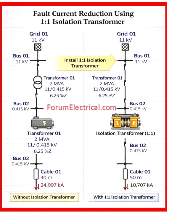
Method-2: Installing a 1:1 Ratio Transformer
A 1:1 isolation transformer can be installed across the feeder cable & the busbar to introduce the transformers impedance into the system.
Principle
Transformer impedance limits the fault current flow.
Example
| Condition | Fault Current |
|---|---|
| Without Transformer | 24.997 kA |
| With 1:1 Transformer | 10.707 kA |
Advantages
- It is an effective fault current reduction.
- It provides electrical isolation.
Limitations
- It requires additional installation space.
- It adds system losses.
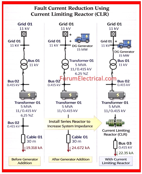
Method-3: Installation of Current Limiting Reactor (CLR) – MV Systems
A CLR – Current Limiting Reactor is connected in series with the systems to increase the impedance and limits short circuit current.
Example
After adding a generator to the system:
| Condition | Fault Current |
|---|---|
| Before Generator | 19.318 kA |
| After Generator Addition | 24.672 kA |
| With Current Limiting Reactor | 22.35 kA |
Increasing the reactor impedance will further reduces the fault current.
Advantages
- Cost effective solution.
- Suitable for MV systems.
- Avoids switchgear replacement.
Disadvantages
- Voltage drop during normal operation.
- It have additional power losses.
- It reduced power factor.
- It requires installation space.
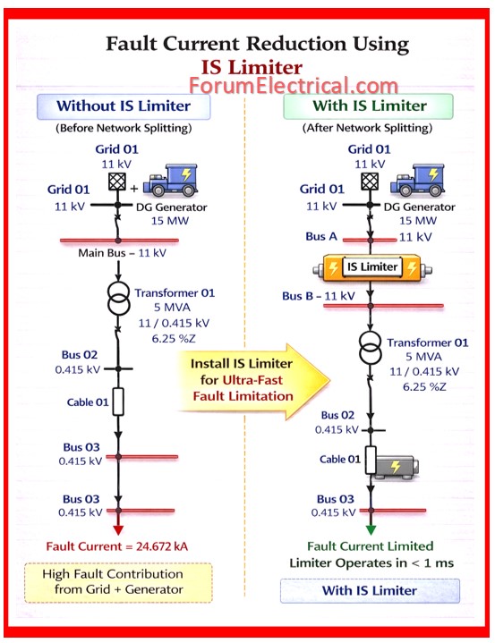
Method-4: Installation of IS Limiter
The IS Limiter is an ultra fast switching device used to limit fault current by rapidly isolating the system.
Principle
> Normal Operation
Current flows through the main conductor.
> Fault Condition
Within < 1 millisecond the device:
- Detects the fault current rise.
- Diverts the current to a high-speed breaking fuse.
- Interrupts the fault current before it reaches peak value.
Advantages
- It is extremely fast operation
- It prevents fault current peak
- It protects existing switchgear
Applications
- Busbar coupling protection
- Limiting distributed generator fault contribution
- Protection of interconnected power systems
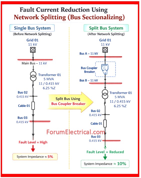
Method-5: Network Splitting (Bus Sectionalizing)
The power system bus can be split into 2 sections using a bus coupler circuit breaker.
Principle
Splitting the network increases system impedance and reduces fault current contribution.
Example
| Condition | System Impedance |
|---|---|
| Single Bus | 5 % |
| Split Bus | 10 % |
Higher impedance results in lower short circuit current levels.
Improved Design Practice
Install individual generator circuit breakers to allow:
- Flexible operation
- Safe maintenance
- Independent generator isolation
Practical Application
In a typical industrial power system:
| Condition | Fault Current |
|---|---|
| Normal Operation | 19.318 kA |
| After Increasing Internal Generation to 15 MW | 24.672 kA |
If mitigation measures are not implemented, it results in:
- Circuit breaker failure may occur.
- Switchgear damage is possible.
- Plant shutdown risk increases.
When fault current exceeds the circuit breaker interrupting capacity the following mitigation measures should be considered:
- Increase system impedance by extending the cable length.
- Install 1:1 ratio transformers.
- Install current limiting reactors.
- Use IS limiters for ultra fast fault limitation.
- Implement network splitting using the bus couplers
- Upgrade switchgear if other solutions are not feasible.
Summary
Short circuit current levels increase as system capacity, generation and interconnections gets developed.
Therefore performing a fault level study is essential before:
- Adding distributed generators.
- Expanding plant capacity.
- Modifying power system configuration.
Proper engineering mitigation ensures:
- Protection of the switchgear.
- Safe system operation.
- Improved reliability of the power distribution network.
