 Switchgear Operation: Safety Precautions and Procedures")
- Introduction
- Hazards of Operating on Electrical Equipment
- Impact of Hazards on Switchgear Operations
- Close Proximity
- Safety Precautions for Medium Voltage Switchgear
- ISITE
- Secure Procedures for Medium Voltage (MV) Switchgear Operation
- Step-1: Switching
- Step-2: Isolation Procedures
- Step-3: Testing
- Step-4: Earthing
Introduction
To be safe while using Medium Voltage equipment, we must adhere to the safety standards and operating requirements. This post discusses general safe operations on the medium voltage equipment, including
- Switching,
- Isolating,
- Testing, and
- Earthing,
and also, the numerous types of medium voltage testers and their applications.
Hazards of Operating on Electrical Equipment
There are five various types of hazards linked with the use of electrical equipment.
1). Electric shock.
2). Electric Burns.
3). Fire & explosion.
4). Increase in Heat
5). Mechanical Hazards.
Electric Shock
It is impossible to detect whether an electrical conductor (or) terminal is alive simply by looking at it; it must be examined with an appropriate approved tester. Then it should be kept safe in such a way that it cannot be electrified by anybody else while being worked on.
Electrical Burns
Medium Voltage does not require contact with a conductor (or) terminal to cause burns. Air does not ordinarily conduct electricity; but, when a human comes too close to an improperly insulated electrical wire, the air can break down & establish a conducting channel between them and the earth. Coils & capacitors store electrical energy & release it once the power is switched off; consequently, they should be depleted before work gets started.
Fire & Explosion
Working with Medium Voltage equipment carries a high risk of fire and explosion due to the huge fault currents that may pass through the system. Oil Circuit Breakers (OCBs), Oil Mini Sub Stations (MSS), & Ring Main Units (RMUs) provide a specific risk. Operator errors may additionally cause faults, such as energizing a wire when the other end is earthed.
Increase in Heat
Heat can accumulate in wires. When a lightweight extension lead is utilized for heavy-duty applications, it becomes hot. Whenever possible, avoid utilizing extension leads. If they must be used, make sure they can handle the current without overheating. Do not string them overhead, across hallways, or beneath mats, where heat might accumulate and fully stretch them.
Mechanical Hazards
Impact of Hazards on Switchgear Operations
Because there is a considerable risk of
- Flashover,
- Shock,
- Arcing, and
- Other hazards
when operating in a Medium Voltage setting, lower voltages are often regarded with neglection.
Asphyxia and/or cardiac muscle fibrillation can occur at voltages as low as 50 volts and currents of ± 30 milliamps.
The most dangerous aspect of electricity is that live & dead apparatus are unrecognizable.
As a result, never assume that apparatus is dead; instead, assume that it is alive. This can only be determined by safety testing with the relevant certified tester or the presence of a visible earth connection.
Electricity can leap gaps; thus, you don’t even have to contact a Medium Voltage conductor to get wounded. Approaching too close can be fatal, therefore keep close proximity distances.
Close Proximity
Close Proximity is the shortest distance that any portion of a person’s body or work tool can come into contact with an unearthed LV conductor or an unearthed & unscreened MV/HV conductor.
| Voltage Rating | Clearance |
| < or = 11 KV | 0.2m |
| 11 KV to 33 KV | 0.43m |
| 11 KV to 132 KV | 1.45m |
| 11 KV to 275 KV | 2.35m |
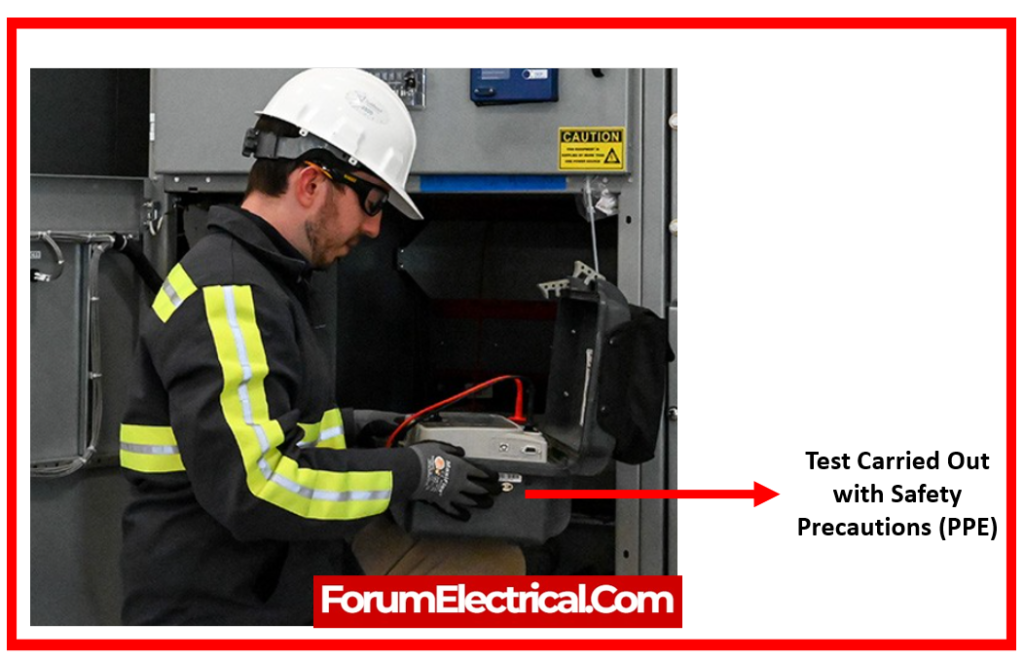
Safety Precautions for Medium Voltage Switchgear
Personal Protection Equipment (PPE)
When working in a potentially hazardous environment, always wear the PPE listed below, as mandated by the Code of Safe Practices.
- Flame-resistant apparel (FR)
- Hood and smock
- Hand protection
- Eye protection
- Hard Hat
Code of Safe Procedures describes potentially unsafe conditions.
Minimum Safe Working Distance
Some enclosures keep powered, high-voltage equipment in easy reach.
Access enclosures containing energized, high-voltage equipment for visual examination only.
Maintain a safe working distance from the energized equipment as prescribed in the Code of Safe Practices, Section 809, “Approach and Working Distance.”
Before unlocking and accessing any compartments, consider all equipment inside as electrified, unless and until it has been cleared, high-voltage tested when de-powered, and the property grounded.
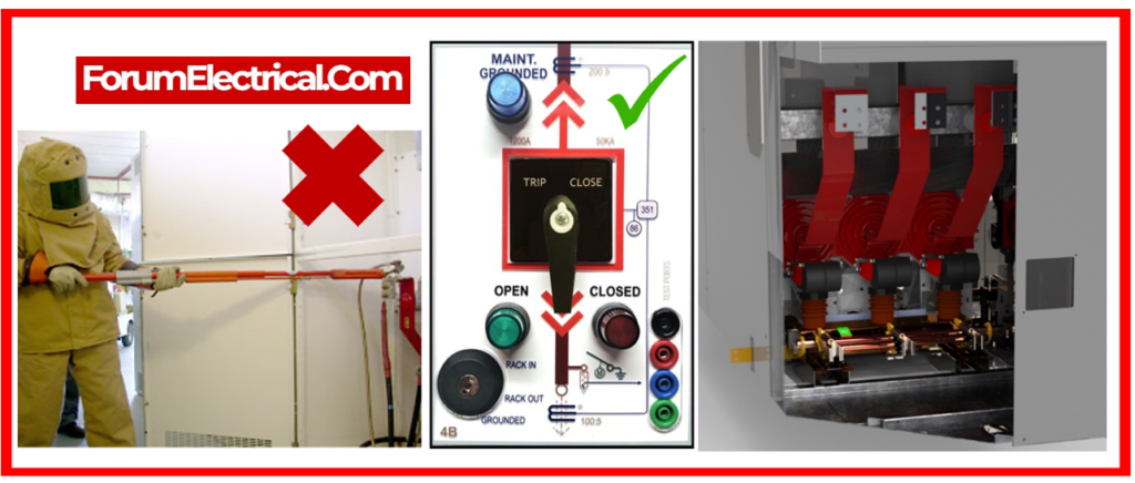
Use Remote Racking Equipment
Remote racking devices enable the removal & insertion of the metal-clad breakers from an electrified bus while the equipment operator remains beyond the arc-flash boundary.
Remote racking equipment, like metal-clad switchgear, vary, thus understanding their individual properties is essential. Before using remote racking equipment, follow the instructions provided by the manufacturer.
Utilizing the Maintenance Slow Closing Device
The maintenance slow-closing device should not be used to manually close any type of circuit breaker that is powered at the primary voltage. The slow-closing device lacking enough force & speed to ensure safe & proper operation.
Precautions for vacuum metal-clad switchgear
Although the maintenance methods for the vacuum metal-clad switchgear are identical to those for other electrical devices, two regions demand additional care.
During normal operation & high-pot (HIPOT) tests, the primary shield in an interrupter, along with other high-voltage components, can accumulate electrical charges.
The shield is linked to the insulating bottle’s external mid-band ring. These charges typically stay after high voltage is withdrawn.
To remove charge before touching
- Interrupter,
- Connections,
- Circuit breaker studs,
- Bushings,
- Ground the bushings and
- Mid-band ring with a clip jumper.
Protection against High Voltage
Don’t depend on the insulation covering the connectors & bus conductors in the metal-clad equipment to protect employees from excessive voltage.
Always assume high-voltage equipment is energized until it has been tested dead & subsequently grounded.
Grounding Bus Sections
Cleared bus portions in certain indoor stations might extend across multiple cubicles or levels.
Before operating on or near equipment in cubicles (or) on floors where the ground is not visible, make sure it is deenergized.
Install grounds as close to the work site as possible.
Certain circumstances necessitate numerous ground sites to ensure personal safety.
Before reporting off and turning on the equipment, make sure that the grounds have been cleared from all areas.
ISITE
I – Determine the correct operational location & correct operating device.
S – Switch
I – Isolate
T- Test
E – Earth
- Identify the appropriate substation/MSS, etc.
- Select the correct circuit breaker or isolator.
- Open circuit breaker/isolator.
- To isolate the circuit breaker, rack it out or down.
- Test with an authorized voltage detector.
- Connect effectively to the earth using the suitable methods.
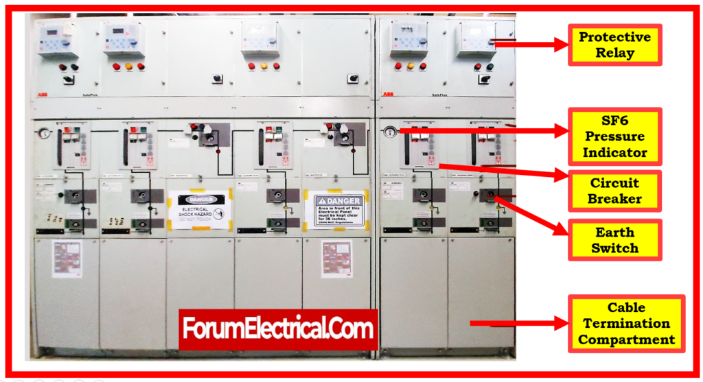
Secure Procedures for Medium Voltage (MV) Switchgear Operation
Step-1: Switching
Circuit Breaker Switch
Circuit breakers are able to be opened in a variety of ways; remote operation is preferable.
Local:
Remote:
Utilizing remote operating panel, remote operating device, and SCADA (Supervisory Control and Data Acquisition).
Circuit breakers must be opened remotely whenever possible. If the procedure will take place locally at the panel, it is advised that the proper Personal Protective Equipment (PPE) be worn (Flash Suit).
Panel Switch
- Mini Sub Stations (MSS) &
- Ring Main Units (RMU)
are manually opened with the appropriate operational handle.
They can also be equipped with an electrical remote operating mechanism, similar to a circuit breaker.
Step-2: Isolation Procedures
Control Point
A location on the system where a main (or) equipment can be switched, isolated, and grounded.
When isolating, the equipment needs to be disconnected from all potential sources of energy, not simply electricity.
As a result, we must evaluate the sources of harmful energy and compounds listed below.
Hazardous Energy
- Electrical, pneumatic, hydraulic,
- Stored (springs, batteries). Potential (because of position),
- Heat (hot water, steam),
- Radiation.
Hazardous Chemicals
- Gases, vapours, liquids, & dusts that have the potential to induce injury or sickness, such as toxic, corrosive, or combustible.
- All plant and equipment require written isolation procedures; these procedures will outline a step-by-step process for isolating and keeping the system, plant, or equipment safe.
- In conditions of electrical isolation, a voltage test must be performed using an appropriate authorized tester to check that the mains and/or device are dead.
- Authorized Isolation is performed in accordance with rules and regulations. Control points need to be locked with personal locks.
- Danger tags need to be placed at all sites of isolation.
Locking off Live Shutters
All live shutters must be locked with a personal lock.

Cable shutters must be classified as live shutters since the cable might be back fed, for example, through an open point on a ring; thus, both bus bar & cable shutters must be locked.
Step-3: Testing
Before applying earthing equipment, the conductor must be examined to ensure it is dead.
Any certified Medium Voltage equipment should be visually examined for faults prior to use.
When testing Medium Voltage, use the three-point test: test the tester on a known live source (or) a manufacturer-supplied test box, test all three phases, and then retest the tester.
There are various varieties of voltage testers on the market, and each has a specific use:
Voltage Detector (Live Tester)
Used to determine the existence of voltage. A live tester must touch the conductor being tested in order to identify whether it is alive or dead. There are two types of live testers: S and L.
- S type – for use with switchgear.
- L-type – for use on overhead lines.
Phase Comparison/Phasing Sticks (Live Tester)
Used to ensure that circuits remain in phase with one another. A phase comparator must be used to compare phases rather than to detect voltages. Ring feeds are being phased in.
It is necessary to phase in medium voltage equipment before energizing cable circuits to ensure proper phase rotation when cable networks are maintained and extended.
Electrical phasing is necessary for new equipment installations that require breaking into a ring feed, such as new substations.
After repairing a ring feed cable, or while terminating one. · Connecting and/or terminating an existing cable that will be returned to service.
Voltage Detector (Proximity Tester)
Used for overhead lines. This tester does not need to make contact with conductor under test to identify whether it is alive or dead; it detects the magnetic field and so only operates on bare and unscreened conductors.
Step-4: Earthing
Connected to the earth’s main mass in such a way that an immediate and safe discharge of the electricity is always possible. There are various distinct earthing methods:
- Integral Earthing
- Earthing Carriage
- Earthing Truck
- Portable Earths
Earthing Carriages are typically used to ground bus bars and use the circuit breaker which has been disconnected.
Earthing Trucks are typically utilized to ground the circuit racks after the circuit breaker has been completely removed.
Portable earths are typically utilized on overhead wires (or) as working earths when work is being done distant from wherever the control point earths have been installed, such as capacitor banks.

 Switchgear. Learn how to maintain safety during handling & operation.)