")
The stability test of a power transformer is done to verify that the transformer differential protection relay remains stable (does not operate) during
- Purpose of Transformer Stability Test
- Principle of Differential Protection
- 1). Through Fault Stability Test
- 2). Load Stability Test
- 3). CT Polarity and Ratio Stability Test
- Test Equipment Required
- Stability Test Procedure
- Step-1: Isolate Protection System
- Step-2: Verify CT Connections
- Step-3: Inject Equal Current in Both Sides
- Step-4: Observe Differential Current
- Step-5: Increase through Current
- Step-6: Record Relay Readings
- Acceptance Criteria
- Causes of Stability Failure
- Importance of Stability Test
- Difference between Stability Test and Operation Test
- Normal load conditions,
- External faults and
- Through fault currents.
In simple terms the test confirms that the differential relay does not trip when the currents entering and leaving the transformer are equal.
Purpose of Transformer Stability Test
The stability test ensures that:
• The differential protection relay does not trip for the external faults.
• The CT ratios and polarity are correct.
• The relay settings are coordinated with the CT ratios.
• No false differential current determined during load conditions.
This is an important verification step during:
- Transformer commissioning,
- Protection relay testing and
- Substation maintenance.
Principle of Differential Protection
Transformer differential protection works on the principle of Kirchhoff’s Current Law.
Concept
Idiff = I1−I2
Where
I1 − Current entering transformer
I2 − Current leaving transformer
If:
I1 = I2
Then:
Idiff = 0
So the relay should be remain stable (no trip).
If an internal fault occurs the currents become unequal:
Idiff > Setting
The relay operates and trips the breaker.
Types of Transformer Stability Tests
There are 3 types of transformer stability tests:
1). Through Fault Stability Test
2). Load Stability Test
3). CT Polarity and Ratio Stability Test
1). Through Fault Stability Test
Through fault stability test checks relay stability when a large current flows through the transformer during external faults.
2). Load Stability Test
Load stability test ensures that the relay does not operate during normal load current.
3). CT Polarity and Ratio Stability Test
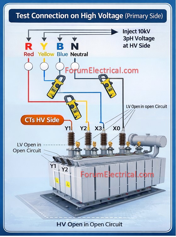
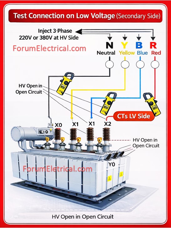
CT polarity and ratio stability test confirms that the current transformers (CT) are correctly connected.
Test Equipment Required
Typical equipment utilized are:
• Primary current injection test set,
• Secondary injection test kit,
• Clamp meter,
• Multimeter,
• Protection relay test kit (OMICRON / Megger / Doble),
• CT test leads and
• Wiring diagram of transformer protection scheme.
Stability Test Procedure
Step-1: Isolate Protection System
- Ensure transformer is isolated or under test condition.
- Disable trip circuit to avoid breaker operation.
- Inform control room.
Step-2: Verify CT Connections
Check:
• CT ratio,
• CT polarity,
• CT secondary wiring,
• CT star point connection.
Incorrect CT polarity is the most common cause of the differential protection maloperation.
Step-3: Inject Equal Current in Both Sides
Using a primary injection kit inject current such that:
Iprimary = Isecondary x (CT ratio/Transformer ratio)
The relay should see balanced current.
Example
Transformer: 10 MVA, 110/33 kV
CT ratios:
HV side = 200/1 A
LV side = 600/1 A
Injected current should produce equal current at relay input.
Step-4: Observe Differential Current
Monitor relay parameters:
- Differential current,
- Bias current,
- Relay trip status.
Expected result:
Differential current ≈ 0 A
Relay should not trip.
Step-5: Increase through Current
Gradually increase injected current.
Example test levels:
- 25% rated current
- 50% rated current
- 75% rated current
- 100% rated current
The relay must remain stable for all currents.
Step-6: Record Relay Readings
Record:
| Test Current | HV Current | LV Current | Differential Current | Relay Status |
|---|---|---|---|---|
| 25% | Value | Value | ≈0 | Stable |
| 50% | Value | Value | ≈0 | Stable |
| 100% | Value | Value | ≈0 | Stable |
Acceptance Criteria
The transformer differential protection is considered stable if:
- No relay trip occurs.
- Differential current remains within relay threshold.
- Bias characteristic remains within limits.
Typical acceptable value:
Idiff < 0.2In
It depends on relay setting.
Causes of Stability Failure
If the relay operates during the stability test the possible reasons include:
1). Wrong CT Polarity
The opposite polarity creates false differential current.
2). CT Ratio Mismatch
Example:
HV CT = 200/1
LV CT = 400/1
The improper compensation creates imbalance.
3). Incorrect Vector Group Compensation
Example:
Transformer vector group:
- Dyn11
- Yd1
The relay must compensate for 30° phase shift.
4). CT Saturation
During high through faults CT may saturate causing:
Idiff = 0
Importance of Stability Test
Transformer stability testing ensures:
• Protection reliability,
• Avoidance of the false tripping,
• Correct CT (Current Transformer) and relay configuration,
• System security during external faults.
Without proper stability testing a healthy transformer may trip unnecessarily causing the power outages and system instability.
Difference between Stability Test and Operation Test
| Parameter | Stability Test | Operation Test |
|---|---|---|
| Purpose | Check relay does NOT trip | Check relay trips |
| Fault Type | External fault | Internal fault |
| Current Condition | Balanced | Unbalanced |
| Result | Relay stable | Relay operates |
The stability test of power transformer verifies that the differential protection relay may remain stable during balanced current conditions and external faults without any unwanted tripping.