 Testing and Commissioning Procedure")
Purpose
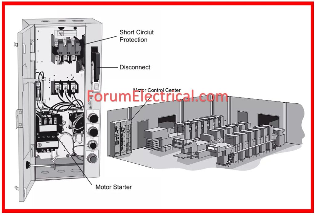
The purpose of this secure work method statement procedure is to define a step-by-step method for implementing the correct practices for the pre-commissioning and commissioning of Motor Control Centers using the guidelines contained herein, ensuring that the work execution meets with the project requirements as well as serves the intended function satisfactorily.
Required Tools
1). Portable Hand Tools
2). Step Ladder
3). HV Testing Kit
4). Secondary Injection Kit
5). Insulation Resistance (IR) Tester
6). Multimeter
Pre-Commissioning Procedure for the Motor Control Center
2). Verify that no damage occurred between mechanical completion and pre-commissioning.
3). Repair or replace any damaged components.
4). Ensure the installation area is free of water and construction debris.
5). Ensure MCCs are properly labeled and identified by location and service, as stated.
6). Ensure all wiring terminations to the Motor Control Center (MCC) are tight and secure.
7). Ensure that all outbound cables (power and control) from the MCC are correctly terminated, marked, and recognized.
8). Ensure the Motor Control Center (MCC) has been properly earthed.
9). Ensure all BMS wiring is completed.
10). Ensure wires to the Motor Control Center (MCC) are correctly marked and identifiable.
11). Check the rating of breakers (ACB, MCCB, MCB, and ELCB). Relays, contactors, timers, and other components adhere to approved shop designs and schedules.
12). Select and set overload relays based on the connected load.
13). Ensure emergency stop switches are available.
14). Ensure adequate metering connections.
15). Manually check the breakers of all cubicles in the MCC.
16). Verify the electrical and mechanical interlocks between the star and delta starters.
17). Ensure cubicles slide smoothly in tracks for all draw-out components.
18). Use a torque wrench to ensure cable terminations on bus bars are tightened to the proper torque.
MCC Testing
Insulation Resistance Test (IR Test)
1). Isolate all incoming and outgoing cables.
2). Apply 500 V DC between phase ‘R’ and Earth for 1 minute, while shorting and earthing phases Y, B, and N. Record the results.
3). Repeat the test for the other phases.
Power Frequency Voltage Test
1). Connect the HV lead from the step-up transformer to R-phase.
2). Shorten the Y and B phases & connect to Earth. Also, connect the enclosure to ground.
3). Turn on the HV test kit control unit and progressively increase the suggested test voltage to R-phase for 1 minute, while keeping other phases earthed and grounded.
4). Record leak current.
5). After 1 minute, gently drop the test voltage to 0 and turn off the HV test kit. Discharge both the pole and the HV test kit.
6). Repeat the test for Y-phase and B-phase and tabulate findings.
Secondary Injection Test
1). Verify tightness of secondary connections in all metering circuits.
2). Using a secondary injection kit, inject nominal secondary values gradually into the power scheme and tabulate output values based on meter ratings.
Commissioning Procedure for the Motor Control Center (MCC)
1). Make sure that all of the pre-commissioning inspections are successfully completed.
2). Measure the incoming supply of the MCC – Motor Control Center for current, voltage, frequency, and phase sequence.
3). Energize the outgoing feeders individually and measure the supply voltage.
4). Verify metering features for appropriate operation and accurate readings.
5). Verify starter functionality in manual mode.
6). Simulate starter functionality while retaining the selection switch in AUTO mode.
7). Verify the earth leakage trip setting.
8). Verify trip operation of ELCB (if applicable).
9). Verify the incomer trip settings.
10). Check the circuit breakers’ ON/OFF function.
11). Check overload relay settings.
12). Check the timing setting.
Attachments
MCC & PCC Panel Safety Checklist


 testing and commissioning procedure, which includes pre-commissioning inspections, practical tests, and safety procedures to ensure dependable and safe operation.)