")
It is absolutely necessary to perform fault diagnostics on Motor Control Center (MCC) panels as well as starter panels in order to ensure the reliable and productive operation of the electrical systems. MCC panels and starter panels, which are responsible for regulating and securing motors & other electrical loads, are essential components of all industrial & commercial facilities.
Downtime, damaged equipment & even electrical fires can all be avoided if operators are proactive about spotting and fixing problems as soon as they occur.
The following is a list of standard procedures and methods for the fault diagnosis in such panels.
Methods for the Fault Diagnosis
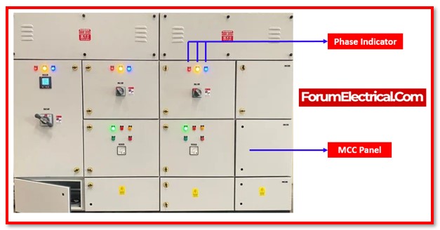
1). Phase indicator
Fault: Lamps for phase indicator are not glowing.
Rectification Measure: Utilizing a voltmeter and a voltmeter selector switch, check to see if the power is available on the upstream side of the incoming supply.
Remarks: No Remarks
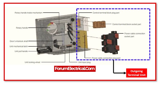
2). Outgoing Terminal
Fault: There is no supply available at the outgoing sections.
Rectification Measure: Check the OFF/TRIP status of the incoming MCCB’s.
Remarks: If it is a trip, then look into the cause of the problem to determine what caused the trip, then reset the trip & turn the power back to ON.
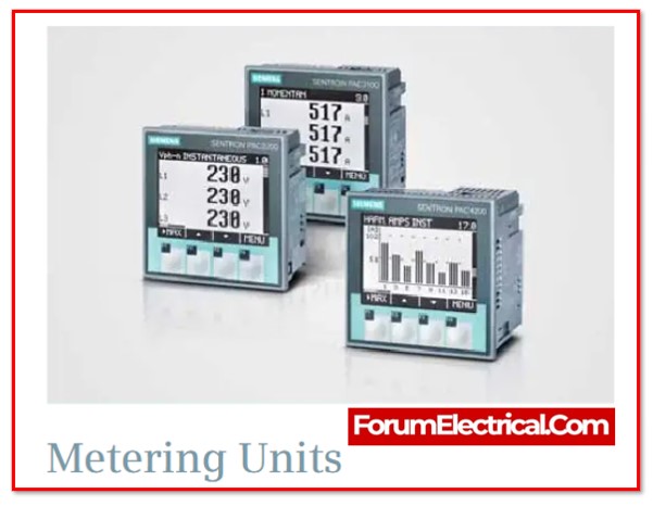
3). Metering Circuits
Fault: There is a fault with the metering circuits and the indication LEDs.
Rectification Measure: Check the fuses that are associated with the controls.
Remarks: Replace it with a fuse that has the appropriate rating, and check it.
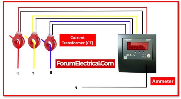
4). Ammeter
Fault: Fault with the ammeter not displaying the correct readings.
Rectification Measure:
- Verify the CT (Current Transformer) short links.
- Verify the CT termination.
Remarks: No Remarks
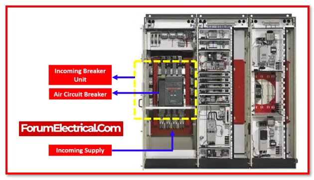
5). Incoming Breaker
Fault: The breaker that protects the incomer is continually tripping.
Rectification Measure: Check the condition of the cable and the load that is included.
Remarks: No Remarks
6). Motor Switching (Manual Operation)
Fault: When in Hand mode, the motor does not turn ON.
Rectification Measure:
- Check the available control voltage.
- Check the conditions of the ON/OFF push buttons.
- Check the Remote lock stop and Emergency stop box.
- Check the position/condition of the normal/bypass selector switch.
- Check that the Fire (FACP– Fire Alarm Control Panel) interlock signal is turned on.
Remarks: No Remarks

7). Motor Switching (Automatic Operation)
Fault: In Auto mode, the motor does not turn ON.
Rectification Measure:
- Check the available control voltage.
- Check the location and condition of the H-O-A selector switch.
- Check the Remote lock stop and Emergency stop box.
- Check the position/condition of the normal/bypass selector switch.
- Examine the ON/OFF Command signal coming from the BMS terminals.
- Verify the VFD/Starter TRIP.
- Check the attached load and cables.
- Check that the OLR rating parameters correspond to the load current.
- Check that the Fire (FACP) interlock signal is turned on.
- Check the BMS Speed reference (0-10VDC) signal.

8). Overload
Fault: An overload happens when the panel is subjected to an excessive demand for current. This can result in the panel overheating, which will cause the circuit breaker to trip.
Rectification Measure: It is important to not overload the MCC and starting panels. Do not use the panel’s maximum allowable current.
Remarks: Electrical faults like short circuits, overloads, and ground faults can be identified using voltage and current measurements.
9). Burned-out components
Fault: Components that have been burned out can lead to a malfunction in the panel or the tripping of the circuit breaker.
Rectification Measure: Check and maintain the starter and MCC panels on a regular basis. This involves searching for damaged wires, burned-out components, and loose connections.
Remarks: A multimeter can also be used to test the components (each part) for continuity.
- Replace the faulty component.
- Determine and rectify the root cause of the failure.

 panels and starter panels are essential to many electrical systems. They can be complex and error-prone. This post will cover the most common MCC and starting panel faults and how to identify and fix them.)