
- What is the purpose of Capacitor Bank?
- Why is testing done on Capacitor Banks?
- How are Capacitor Bank Tests Performed?
- Type Tests (or) Design Tests
- Routine Capacitor Bank Test
- Pre-Commissioning Test (or) installation test of the Capacitor Bank
- How are Capacitor Banks Tested?
- Primary Injection Test
- Pre-Commissioning Checklist
- Charge and Perform Load Tests
- Advantages of Capacitor Bank Testing
- Why do Capacitor Banks Fail?
- Does Capacitor Bank reduce Power Consumption?
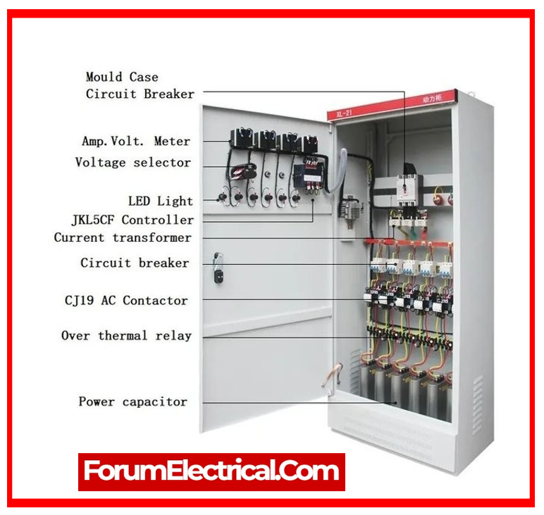
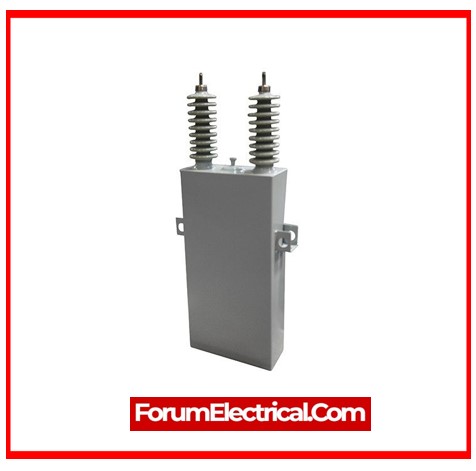
A capacitor bank is a collection of capacitors of comparable ratings connected in parallel (or) series to gather electrical energy.
The resulting bank is then applied to an alternating current power source in order to rectify or compensate for phase shift or power factor lag.
They can also be used in a DC power supply to increase the overall quantity of stored energy or the power supply’s ripple current capacity.
A capacitor bank collects and stores electrical energy in order to eventually meet an operational requirement while also ensuring adequate power factor levels for the electrical system.
It is necessary to test the capacitor bank at regular intervals to ensure its performance & reliability.
A capacitor bank, as static equipment, must be examined to ensure proper maintenance. If not properly maintained, they can constitute a serious hazard to the industry in which they are employed.
As a result, it is required to conduct a capacitor bank test on a regular basis to make sure the capacitor bank’s safety.
Capacitor banks are commonly utilized in
- Power Factor Correction
- Reactive Power Compensation
Capacitors, unlike inductive motors, balance out immense current flow, resulting in a lower electricity bill.
What is the purpose of Capacitor Bank?
Capacitor banks store electrical energy in their components and use it to correct power factor lags (or) phase shifts in an alternating current (AC) power supply. This assists in maintaining optimum efficiency & prevents unwanted dips (or) surges in voltage that can harm electrical equipment.
Why is testing done on Capacitor Banks?
An essential component of any power system that can provide accurate power factor correction are capacitor banks. Depending on where they are located, power factor correction units can operate in different ways. Temperature, time, harmonics, and moisture all affect the way capacitor banks compensate for power factor.
Installed capacitor banks lose their ability to operate at optimal efficiency if they are not tested or maintained within a certain period of time.
Capacitor functioning can deteriorate over time, lowering your power system’s power factor and leading to power factor loss.
How are Capacitor Bank Tests Performed?
An ANSI or IEEE standard is used for testing a capacitor banks. Tests on capacitor banks are conducted in three different ways.
These are
- Type Tests (or) Design Tests
- Routine Tests (or) Production Tests
- Pre-commissioning Tests (or) Field Tests
Type Tests (or) Design Tests
When a company introduces a new design of power capacitor, the new batch of capacitors must be tested to see if they meet the standards. Type tests (or) design tests are not performed on a single capacitor, but rather on a group of randomly selected capacitors to ensure compliance with the standard.
Once these design tests are completed during the introduction of a new design, they do not need to be repeated for any subsequent batch of manufacturing till the design is changed. Design tests and type tests are typically expensive or damaging.
The type tests performed on the capacitor bank are:
- High Voltage Impulse Withstand Test.
- Bushing Test.
- Thermal Stability Test.
- Radio Influence Voltage (RIV) test.
- Voltage Decay Tests.
- Short Circuit Discharge Test.
1). High Voltage Impulse Withstand Test
This test validates that the insulation used in the capacitor unit has the necessary withstand capability. The insulation of the capacitor unit must be able to tolerate high voltages during transient overvoltage conditions.
There are three kinds of capacitor units.
a). Single Bushing Capacitor unit
One terminal of the capacitor element exits the casting via a bushing, while the other terminal is directly linked to the cashing itself.
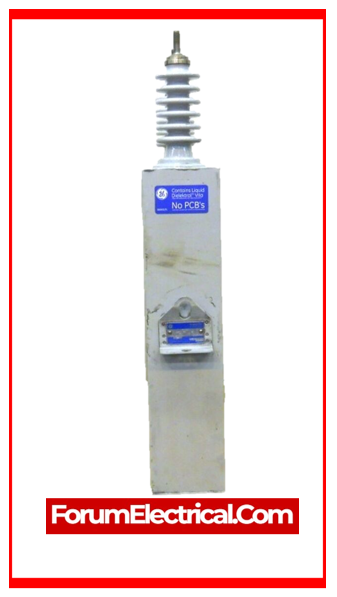
The cashing of the capacitor unit operates as one terminal of the capacitor unit, which is connected to the bushing stand via the capacitor elements.
The high voltage impulse with stand test will not be done on this unit.
b). Double Bushing Capacitor Unit
The two ends of the capacitor element are terminated on cashing using two different bushings. Here, the cashing is completely separate from the cashing body.
c). Three Bushing Capacitor Unit
In a 3-phase capacitor unit, the line terminals of each phase of three phase capacitor elements emerge from the casing via three distinct bushings.

2). Bushing Test
If there was no flashover in the prior impulse test, there is no requirement for a separate bushing test.
However, if a flashover occurs during the first three consecutive applications of impulse over voltage, the remaining three over voltages are applied.
If no additional flashover occurs in bushing, it is considered to have passed the test.
3). Thermal Stability Test
This test determines capacitor unit thermal stability. Test unit is positioned between two dummy capacitors for this test. Test and dummy capacitors must be the same size.
The dummy and test units should be mounted like the capacitor bank arrangement.
All three capacitors are enclosed to decrease airflow.
Dummy units may be capacitor or resistor models of the test unit. Resistor model uses resistors inside capacitor casings to provide the same thermal impact as capacitors for the same power.
Forced air circulation inside the enclosure is prohibited. The formula below calculates a test voltage that energizes the test capacitor & 2 dummy capacitors.
VT = 1.11VR√(WM/WA)
In this equation,
VT represents test voltage,
VR represents rated voltage,
WM represents maximum permissible power loss, and
WA represents actual power loss.
The test voltage is calculated from the preceding calculation; however it should not exceed 144% of the capacitor unit’s rated KVAR.
The calculated or predicted voltage must be maintained within ±2% for the whole 24-hour test period.
4). Radio Influence Voltage Test
This capacitor is tested at rated frequency & 115% of rated rms voltage. This test is only done on units with several bushings.
Because one bushing unit casing connects directly to capacitors. The multi bushing unit casing must be earthed during testing.
Dry and clean the test capacitor bushing and keep it at room temperature. The item should be mounted as indicated. When measuring at 1 MHz, the radio frequency voltage should not exceed 250 µv.
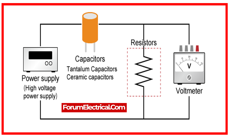
5). Voltage Decay Test
Here, the capacitor unit is replaced with direct voltage equal to its peak rated alternating voltage.
After charging, discharge the unit and monitor voltage decay. In the voltage decay test, a capacitor unit rated over 600 V(RMS) passes if the voltage drops below 50 V in 5 min.
Capacitors under 600 V(RMS) should degrade within 1 min.
6). Short Circuit Discharge Test
This test checks all capacitor unit internal connections for tightness. Tightness and conductor size and electrical qualities are checked in a capacitor unit.
This test charges capacitors to 2.5 times their rated rms voltage. Discharge the capacitor. At least 5 charges and discharges are needed. Before charging and after fifth discharge, the capacitor unit’s capacitance is measured.
The difference between initial & final capacitance should not exceed the unit’s capacitance differential when one capacitor or fuse is shorted.
(Initially recorded capacitance – capacitance measured after 5th discharge) < (capacitance of unit with all elements & fuse element – capacitance with one capacitor element shorted or one fuse element activated)
Routine Capacitor Bank Test
Routine testing are sometimes known as production tests. These tests need to be conducted on each capacitor unit in a manufacturing batch to ensure that each has an independent performance parameter.
1). Short Time Overvoltage Test
In this test, a direct voltage of 4.3 times the rated rms voltage or an alternating voltage of 2 times the rated rms voltage is supplied to the capacitor unit’s bushings.
The capacitor range must be able to endure all of these voltages for at least 10 seconds. The unit’s temperature during testing should be kept at 25 ± 5 degrees. If three phase capacitors are linked in a star configuration, with neutral connected via a fourth bushing or casing, the voltage applied across phase terminals will be √3 times the voltages described above. The same voltage as above could be applied across the phase and neutral terminals.
2). Terminal to Case Voltage Test
This test is only applicable when the internal capacitor elements of a unit are separated from its housing.
This ensures that the insulation provided between the capacitor parts and the metal enclosure can tolerate overvoltage.
The test voltage is applied across the casing and the bushing stand for ten seconds. For capacitor units with bushings of differing BIL, this test is performed on the lower BIL bushing.

3). Capacitance Test
This test ensures that each capacitor unit in a batch (or) lot does not exceed 110% of its rated VAR during normal operation within the temperature limit of ˚C.
If the measurement is done at a temperature other than 25˚C, the final result should be computed using 25˚C.
4). Leakage test of Capacitor Units
This test is performed to check that the limit is free of any leaks. In this test, an external oven heats the test unit to drive the insulating liquid out of the case if there is a leaking site.
This test ensures that all joints are tightened & sealed properly.
This test ensures that all joints are tightened & sealed properly.
5). Discharge Resistor Test
This test is performed on each capacitor unit to check that the internal discharge device (or) resistor is capable of reducing the capacitor unit’s initial residual voltage to 50 V or less within the given time limit.
The first residual voltage can be √2 times the capacitor’s rated rms voltage.
6). Loss Determination Test
This test is done on each capacitor unit to ensure that the loss experienced when operation is less than the unit’s maximum permissible loss.
7). Fuse Capability Test of Internal Fused Capacitor Unit
In this test, the capacitor unit is initially charged with the direct voltage (DC) up to 1.7 times its rated rms voltage.
The unit can then discharge across a gap as close as feasible to the discharge circuit without adding any more impedance. The capacitance of the capacitor must be measured both before and after applying the charging voltage.
The variance of these two measures should be less than the fluctuation of capacitance whenever an internal fuse element is engaged.
Pre-Commissioning Test (or) installation test of the Capacitor Bank
When a capacitor bank is accurately built on location, some specific tests must be undertaken to confirm that the connections between each unit & the bank are correct and in accordance with specifications.
1). Capacitance Measurement
For measuring the capacitance of the bank as a whole, a sensitive capacitance meter is utilized to ensure that the bank is properly connected.
If the measured value differs from the estimated value, there is a problem with the bank connection that needs to be fixed. We should use the full rated voltage to get the capacitance of a bank, rather than merely 10% of the rated voltage to obtain the capacitance of the unit.
The capacitance formula is as follows:
V = 1/cω
c = 1/Vω
In the equation,
V – Applied Voltage to the Bank,
I – Supply Current, and
ω = 377.7, a constant quality.
2). High Voltage Insulation Test
This test is performed in accordance with NBMA CP-1.
How are Capacitor Banks Tested?
Conduct an On-Site Risk Assessment
- Before completing this task, any hazards to the site must be recognized and addressed with appropriate control measures.
- If any dangers cannot be reduced or controlled to an acceptable level, do not proceed with the task & seek advice from the supervisor.
- All work to be completed with the capacitor bank de-energized.
- All testing should be performed with the capacitor bank de-energized & suitable control systems in place to avoid accidental interaction with neighboring live plant or crossing exclusion zones.
- Issue a test permit & fulfill P53’s rules for operating the network process.
According to substation primary plants & secondary systems field testing, the safety issues associated with capacitors are:
- Contact with high voltage at the capacitor bank primary connectors.
- Extreme fault current.
- Stored energy in the charged capacitors.
- Carry out secondary isolation.
- Evaluate the need to execute secondary isolation of protective system.
- While performing this evaluation, keep in mind the sensitivity of capacitor bank protection, as well as the possibility that a capacitor under test will inevitably discharge stored energy into a protection system.
- In the majority of cases, secondary isolation of the protective system would be required.
Plant Particular Details
- Record the identification details of each capacitor unit.
- Manufacturer’s name
- Manufacturer’s type description
- Manufacturer’s serial number
- Year of manufacturing
- Measured capacitance & rated capacitance Cn, as indicated on the nameplate
- The serial number for each capacitor can
- Rated Output: Qn
- Rated Voltage: Un
- Rated Current: In
- Temperature Category
Visual Inspection of the Capacitor Bank Conditions
- Examine the external surfaces & make sure the capacitors & reactors are clean & dry.
- Check that the primary connections are correct.
- Check the earthing connections between the capacitor bank mounting frames & enclosure.
Measure Insulation Resistance
- Insulation resistance tests, as listed below, will be conducted for one minute each.
- Safety CTs/VTs connected to the bank star point should be removed during these tests.
- When numerous components are linked in parallel, such as capacitor cans, it is not essential to get individual insulation resistance measurements for each component.
- To ensure that the capacitors being evaluated have changed sufficiently to allow for precise IR measurement, make sure to verify that the capacitor has been charged by the megger so that there is less than a 5% change in IR over a 1-minute period.
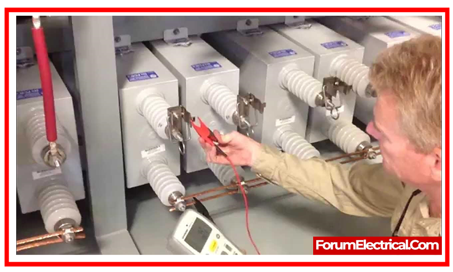
Measure Capacitance
- Use a capacitance bridge to determine the capacitance of every individual capacitor unit. Any test equipment must be operated in accordance with the operating instructions for the individual equipment being utilized.
- Tong type capacitance bridges can typically be used without detaching the capacitor units from the bank.
- It is preferable not to detach the capacitor units for measurements to avoid inadvertent damage to the capacitor unit bushings.
- It is important to note that bushings have accurate maximum torque limitations that must not be exceeded while tightening connections.
- On the other end, an AC current source should be connected to a capacitor unit in series.
- To determine capacitance, use the formula
C = I / (2 x Pi x f x V)
Where,
C represents capacitance in farads.
V represents induced voltage in volts.
I represents the injected current in amps.
f represents the frequency of injected current.
- The capacitance calculation should be performed during a period when the temperature is uniform across the bank
Measure Reactance
- Measure the reactance of inrush limiting or tuning reactors.
- To compute reactance, input a large alternating current and measure the voltage across the reactor, then use the formula
Z = V / I
Where,
Z represents reactance in ohms.
V represents induced voltage in volts.
I represents the injected current in amps.
- The resistive component of impedance is excluded in this formula, which simplifies most reactors (air-cored reactors have Q > 40).
- Conduct High Voltage Test
- High voltage AC & DC testing of capacitors is only required if the owner requests it, and it is often requested only when there are manufacturing or batch concerns to resolve.
- Alternatively, it may be necessary at the commissioning engineer’s discretion when a decommissioned bank is reinstated to service. A capacitor must survive a 10-second DC test voltage supplied between its primary terminals.
- To apply the voltage level, use the equation:
UTest = Un x 4.3 x 0.75.
Where,
UTest represents the applied test voltage.
Un stands for the capacitor’s rated voltage.
- The capacitor must also pass a one-minute power frequency withstand test with a test voltage applied across the capacitor terminals & earth.
Verify Balancing of Each Bank
- Check the balance of each bank by entering the observed capacitance amount into an appropriate balancing application.
- Where necessary, swap cans are used to establish appropriate bank balancing.
Primary Injection Test
- Bridge out the bank capacitor cans & inject through appropriate CTs with a low voltage current source to test bank unit protection methods.
- If primary injection is needed to verify capacitor bank balance, do so when the bank temperature is stable and consistent.
- Use a balanced three-phase source in the bank’s input terminals to determine:
- Voltage applied to each phase (phase-to-phase and neutral).
- Line current per phase.
- Compared to neutral, capacitor bank star voltage.
- Voltage/current at out-of-balance protection.
- Secondary current coming from each CT core that is used for metering and protection. Check that any out of balance current/voltage, scaled from primary injection test voltage to actually rated voltage, is below the alarm or trip threshold.
Pre-Commissioning Checklist
- Check for transit damage and proper assembly of sheet metal.
- Make sure all permanent panels are bolted.
- All door fittings should be tight.
- Make sure door locks work.
- Make sure the paint is clean and scratch-free.
- Verify that all control cable terminations are tight.
- Make sure capacitors are clean and leak-free.
- Torque busbar connections properly.
- Torque capacitor bushing connections properly.
- Verify earth switch functionality.
- Make sure isolator works.
- Check discharge timers, electrical interlocking with the control systems, and HV circuit breakers and switches that can power the bank.
- POW relay operation and adaptive capability should be checked.
- Provide interlock keys.
- Test cubicle illumination.
- Check heater function.
- Verify all fuses/links.
- Make sure CT secondary linkages are closed.
- Check fences and gates outside.
- Make sure labels & nameplates are correct.
- Record SAP/MIMS asset management plant details.
- Test all control & protection functions.
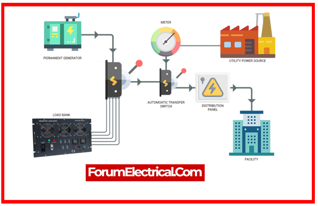
Charge and Perform Load Tests
- All protection & metering secondary circuits’ residual, phase, and out-of-balance secondary currents & voltages should be saved after energization.
- Check and record point-on-wave switching device operation and adaptability. Test energizing may be needed several times.
Advantages of Capacitor Bank Testing
- Reduce the system’s line current.
- Increases the voltage level of load.
- Reduce System Losses.
- Improves the power factor of source current.
- Reduce the load on the alternator.
- Reduce the investment in capital per MW of load.
- Reduce the electricity bill.
Why do Capacitor Banks Fail?
- Resonance between capacitors & other components on the line.
- Poor maintenance causes overheating.
- unexpected load fluctuations create excessive current flow.
- Harmonics produced by nonlinear loads such as computers or LED lighting systems.
Does Capacitor Bank reduce Power Consumption?
When a capacitor system is implemented in a distribution system to increase system power factor, it reduces the magnitude of the current flowing between the conductor & transformer. Consequently, power loss is decreased.