
Power Transformers are developed, manufactured, & tested to high standards, and they are known for their quality and dependability in service.
This post describes the installation, operation, and maintenance of of power transformer.
- Power Transformer Installation
- Installation
- Foundation
- Testing and Commissioning
- Pre-Testing
- Winding Resistance Testing
- Voltage Ratio Testing
- Phase Displacement Testing
- No-Load Loss & Current Testing
- Short Circuit, Impedance & Load Loss Testing
- Temperature Rise Test
- Insulation Resistance Test
- Induced Overvoltage Withstand Test
- Separate-Source Voltage Withstand Test
- Lightning Impulse Test
- Noise Testing
- Commissioning
- Standards for Power Transformer Testing
- Checklist
- Calculator
- Summary
Power Transformer Installation
Installation
The installation site must be easily accessible for inspection. The transformer installation location must be such that the
- Breather,
- Oil level indication,
- Rating and diagram plate,
- Dial thermometers, and
- Other components
may be securely inspected while the transformer is energized.
It should also be possible to access the operational mechanisms of the
- ON/OFF Circuit tap switch,
- Marshalling box, and so on.
The sampling valve, drain valve, and so on should be conveniently located.
When installing transformers indoors, appropriate ventilation and grounding space are required to allow the transformer to adequately dissipate losses.
If enough spacing is not given, the transformer’s temperature will increase, compromising the insulation of windings & the condition of the oil.
Foundation
A transformer installation does not require a special foundation, other than a level floor that is sturdy enough to hold the weight and prevent water from accumulating.
The transformer foundation must be equipped with enough oil soak pits and drains.
For outdoor installations, a level concrete pedestal of the appropriate size to hold the transformer should be constructed so that no one steps on it.
Testing and Commissioning
Pre-Testing
If the preceding instructions were carefully followed, the transformer is ready to be securely placed in service following precommissioning tests.
Tap Changer
Ensure that the taps are turned on at the same time on each phase. Check the mechanical operation of the transformer, particularly the locking system, to ensure that it is satisfactory.
Bushings
Check to see if the line connections were done correctly. Also, ensure that the arcing horn gaps are properly set.
General Checks
- Ensure all oil valves are closed or open as needed.
- Ensure there are no air pockets left in tank.
- Ensure all thermometer compartments are filled with oil.
- Ensure oil levels are correct in the conservator, on-load tap changer tank, and bushings.
- Check for adequate earthing connections.
- Ensure the transformer is securely placed and does not move while in operation.
Winding Resistance Testing
Voltage Ratio Testing
The voltage ratio must be tested on each tapping and verified against a manufacturer-approved power transformer testing technique.
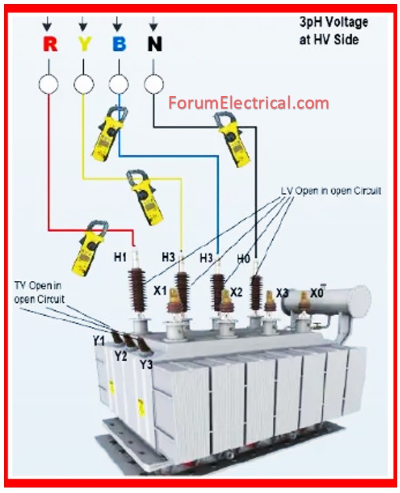
Phase Displacement Testing
The polarity of single-phase transformers and the connection symbol of the three-phase transformers must be checked in each winding.
No-Load Loss & Current Testing
The no-load loss and current are should be tested at the rated voltage & frequency. The waveform of test voltage must be approximately sinusoidal.
Short Circuit, Impedance & Load Loss Testing
The short-circuit impedance & load loss must be tested at the specified frequency and current.
When measuring the rated current is difficult, the test can be performed at lower currents of 50% or more of the rated current.
In this situation, the measured value should be converted to rated current.
Short-circuit impedance should be tested with the windings connected to the major tappings.
In addition, the short-circuit impedance must be tested with the winding connected to both the maximum and lowest tappings.
Temperature Rise Test
The test shall be conducted using any of the following methods:
Direct Loading Method
- A rated load is applied to the transformer windings.
Back-to-Back Method
- The transformer windings get the rated current at the rated voltage.
Equivalent loading Method (Short-Circuit Method)
- To find the temperature rise of oil, provide the transformer with input power equal to the sum of no-load & load losses, with one winding excited and the other short-circuited.
- When the rate of change in top oil temperature rise falls below 1 K per hour, the input is decreased to a value that allows rated current to flow at rated frequency in windings, & this value must be maintained for three (3) hours.
- The temperature of windings is then calculated using the resistance method.
- When the winding has taps, temperature rise tests must be performed at the tap that results in the greatest overall losses.
The temperature rise test must be conducted on the following components:
- Maximum temperature rise of oil
- Temperature rise of core and other metallic parts when specified.
- Temperature rise of windings
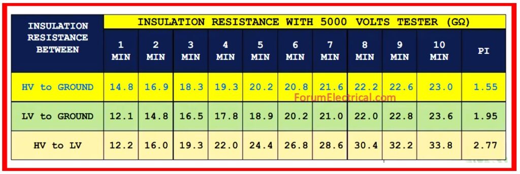
Insulation Resistance Test
The insulation resistance between all transformer windings or other live parts & ground (or casing) must be tested, & the insulation resistance tester & allowable insulation resistance value for every part must be as follows, (or) as specified in the manufacturer’s approved power transformer testing procedure.
Induced Overvoltage Withstand Test
The test shall be performed by providing an alternating voltage to the terminals of one winding of transformer at a frequency greater than the rated frequency and as close to a sinusoidal waveform as practicable.
Separate-Source Voltage Withstand Test
The separate-source voltage test must be performed with single phase alternating voltage as close to sinusoidal wave shape as possible and at any convenient frequency not less than 80% of the rated frequency.
For live portions of accessories (except the on-load tap changer), a test voltage (2E+1 000 V) must be applied for one minute, & no electrical (or) mechanical flaws shall be discovered. (Where E refers to the rated voltage.)
Lightning Impulse Test
The windings on the high voltage side of the transformers built for lightning impulse testing must be subjected to the impulse test voltage specified in the appropriate standard.
Noise Testing
The sound level of the transformers must be measured when specifically stated, such as for power transformers. The measuring method must adhere to the appropriate IEC standards.
Commissioning
- Before commissioning, ensure all pre-commissioning tests and checks are satisfactory.
- Allow a minimum of 24 hours for oil to settle and remove air from all points.
- The transformer can now be activated at no load with tap changer in the normal position, once the protection relays have been set to the least possible.
- Wherever possible, increase the voltage gradually. Check that the primary voltages & currents are in balance.
- Also, check for any excessive noise (or) vibration while commissioning. Following certain hours of energizing with no load, turn off the transformer.
- The Buchholz relay must be tested for the presence of air/gas.
- Abnormalities should be remedied.
- All protective relays must be reset to their regular values. The transformer is now able to progressively turned on and loaded.
- Check that the voltages & currents on HV and LV sides are balanced, then raise the load to the recommended value and ensure that the noise is not excessive.
- A perfect transformer produces a steady hum.
- Observe the operation for some hours.
- If the functioning is satisfactory, the transformer is maintained loaded and voltage and current readings on all phases of both the HV and LV sides are recorded.
- Monitor the temperature of the top oil at the regular intervals.
Standards for Power Transformer Testing
- IEC 60076 – International standard for power transformer testing.
- IS 2026 – Indian standard for power transformer testing.
- BS 171 – British standard for power transformer performance.
Checklist
Power Transformer Installation: A Step-by-Step Checklist
Calculator
- Full Load Current & Turns Ratio Calculator for Transformer
- Transformer Impedance Calculator
- Power Loss Calculator
Summary
Proper power transformer testing ensures that electrical systems are reliable, efficient, and safe. Routine tests such as insulation resistance, oil analysis, and load/no-load tests can uncover potential flaws early, avoiding breakdowns and costly downtime.
Regular maintenance and compliance with industry standards improve transformer performance & lifespan.


