
Specific Data
This particular technical datasheet will detail the transformer(s) that will be responsible for providing energy generation operation.
General Conditions
All of the information contained in this datasheet has to be verified, confirmed, and completed by the provider.
It is necessary to ensure that all working ranges are ensured, regardless of the location of the OLTC, in order for the transformer to function properly in the conditions of the installation site.
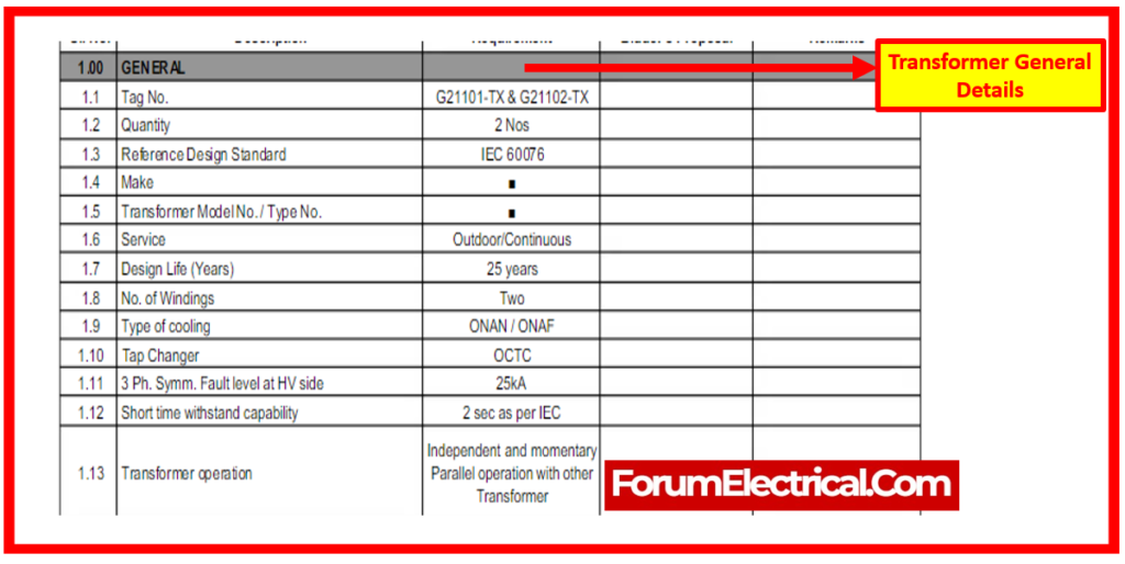
Transformers, labeled with tag number are specified in accordance with the reference design standard IEC 60076.
Intended for outdoor and continuous service, each transformer has a design life of 25 years.
Featuring two windings, the transformers utilize either ONAN or ONAF cooling systems and incorporate OCTC tap changers.
They are capable of withstanding a three-phase symmetrical fault level of 25kA at the high-voltage side for up to 2 seconds, meeting IEC standards.
These transformers are designed for independent and momentary operation, as well as parallel operation with other transformers.
Design Data
The design data for the transformer contains a temperature of 55 degrees Celsius as the design temperature. In contrast, the continuous maximum rating (CMR) for forced cooling is 16 MVA, while the CMR for natural cooling is 12.5 MVA.
With a tolerance of +/-5%, the supply voltage is 33 kV, & the system frequency is 50 Hz, with a range of +/-5%. Both of these variations are possible.
In the absence of load, the voltage ratio is rated at 33/6.9 kV. In addition to impedance levels, the transformer features currents that are set for both ONAN & ONAF circumstances.
An HV delta and an LV star are used for the winding connections, and Dyn11 is the identification given to the vector group.
The high-voltage side of the system is earthed, and the low-voltage side is resistance earthed, for a maximum current of one hundred amperes. The class of insulation is known as Class-A.
The rise in temperature is determined by the conditions of the ambient temperature, which include the temperatures of the winding and the oil. For both high-voltage and low-voltage windings, the basic impulse withstand voltage is stated.
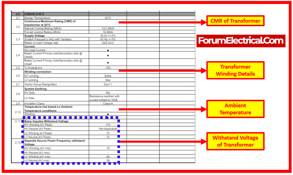
In addition, the high-voltage and low-voltage windings each have their own individual source power frequency withstand voltage.
Environmental Data
Altitude above sea level, transformer position, humidity levels, and temperature characteristics are examples of environmental data for a particular location. 53°C is the highest recorded temperature, and 6°C is the lowest. The 6°C to 53°C temperature range is used in the design. There is not more than 1000 meters above sea level. Transformer locations are not limited to indoor spaces.
With a design humidity of 58%, the highest humidity level that has been observed is 57.5%. Zones 1 and 2, which are designated as hazardous and non-hazardous, make up the area. IIA, IIB, & IIC are the classed groupings.
Additionally provided is the temperature class.
Furthermore, at one meter, the maximum sound pressure level is 85 dBA.
- Maximum temperature: 53°C
- Minimum temperature: 6°C
- Design temperature range: 6°C to 53°C
- Altitude above sea level: less than 1000 meters
- Transformer location: Indoor or Outdoor
- Maximum humidity: 57.5%
- Design humidity: 58%
- Area classification: Hazardous (Zone 1) and Non-Hazardous (Zone 2)
- Group classification: IIA, IIB, IIC
- Temperature class: Not specified
- Maximum sound pressure level at 1m: 85 dBA
Electrical Characteristics
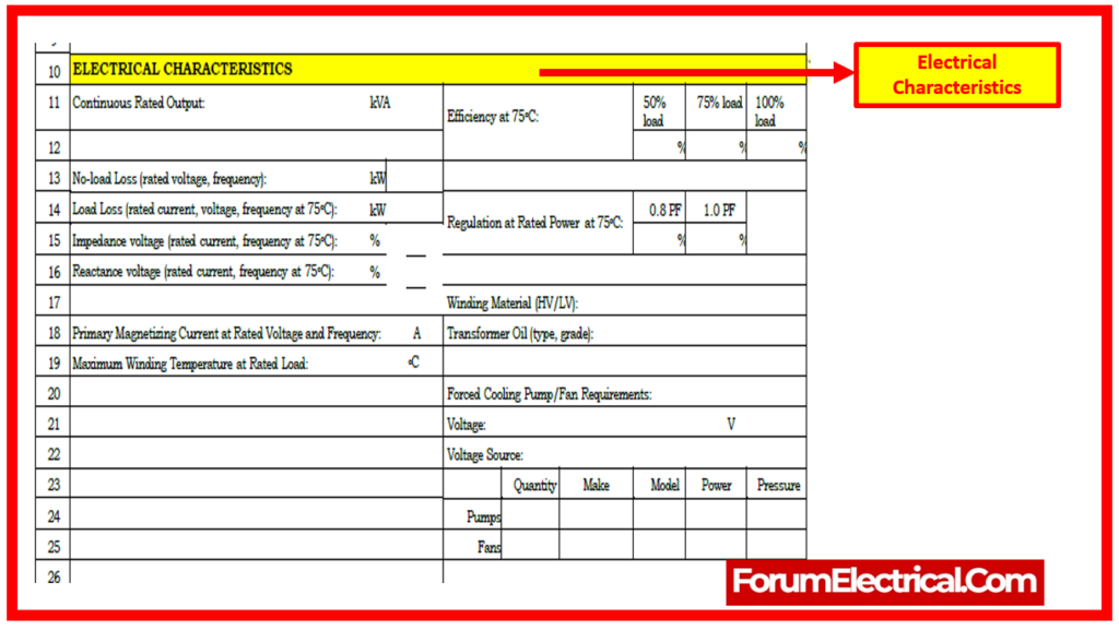
The electrical system has a continuous rated output of 2000 KVA and operates at a primary voltage of 11 W & a secondary voltage of 415 KV.
Its tap changer allows for modifications both on and off the circuit within a tapping range of +/-5%, with 2.5% increments per step.
The system operates at a frequency of 50 Hz, meets insulation class A norms, and maintains a Class A temperature rise classification. It is designed with three phases & a Dyn 11 vector group, uses conservator cooling (ONAN), & is directly earthed for further safety.
Control, Alarms and Accessories
The system has a rated BIL (Basic Insulation Level) of 75 kV and includes essential controls, alarms, and accessories such as oil temperature, winding temperature, oil level, pressure relief vent, lower oil sample valve, upper fill/filter valve, integrated protection relay, & Buchholz relay.
Transformer Arrangement
The configuration of the transformer takes into consideration a number of different aspects, such as the type of transformer tank, the mounting arrangement, the cable specifications, and any other requirements. Mounting selections for the transformer tank include pad mount, pole mount, and other designs that can be required according on the situation. The transformer tank can be of the dry, conservator, or sealed type.
Cable Details
Cable specifications for both primary & secondary windings include XLPE/SWA/PVC insulation type and outside diameter in millimeters.
Other considerations include tropicalization requirements, the option between conventional or alternative protective coatings, & the need for neutral & primary side current transformers.
Datasheet