
Metal-enclosed busways must be tested systematically to ensure compliance with design specifications and regulatory standards. Here’s a brief outline:
PURPOSE
To ensure that metal-enclosed busways are installed according to design specifications and that their characteristics are in applicable standards & manufacturer’s tolerances.
SCOPE
This procedure must be followed when testing metal-enclosed busways on-site.
DEFINITIONS
- C.E – Commissioning Engineer
- C.M – Construction Manager
- T. T – Testing Technician
- Q.C – Quality Control
REFERENCE STANDARDS & CODES
RESPONSIBILITIES
The Commissioning Engineer (C.E.) is responsible for developing the testing method, ensuring that all safety precautions needed and supervising the testing activities.
The Testing Technicians (T.T.) will be in charge of carrying out the tests and recording the test results.
The QC Department is in charge of reviewing test records to ensure that all tests were carried out in line with the approved inspection & test plan.
Test Equipment Control
When the test equipment is delivered to the storage facility, the Commissioning Engineer is responsible for inspecting it. The calibration markings on each component of test equipment must be functional. The test equipment handbook, calibration certificates, and test equipment availability are all the responsibility of the commissioning engineer.
The date of calibration, serial numbers of the test equipment, & copies of the calibration certificates will all be recorded by the commissioning engineer.
Test equipment that is out of calibration must be isolated in a quarantine area and transferred as quickly as feasible to a recognized metrology laboratory for recalibration against national standards, according to the Commissioning Engineer’s instructions.
Before starting any tests, the testing technicians must make sure that the equipment is tested to ensure good operation. Any test equipment that isn’t working properly shall be placed in a quarantine area and fixed as soon as possible.
The QC Department will periodically inspect the testing equipment to make sure that it is entirely within the mandated calibration interval.
Quality Control
The Commissioning Engineer is responsible for developing the testing plan, which includes the devices that need to be tested, the tests to be done, the test equipment to be utilized, the test method to be followed, and the test records to be utilized. A testing schedule will be prepared in collaboration with the Construction Manager based on the testing plan.
The Commissioning Engineer is responsible for organizing, supervising, and verifying the testing schedule’s implementation.
Any defects or deviations from the approved specifications & standards will be documented during testing and reported.
The Testing Technician must utilize the pre-commissioning procedures as checklists & record the testing results. The forms will serve as quality record documentation, proving that the inspection & testing were carried out.
The following tests will be carried out and documented on pre-commissioning forms:
- Visual and mechanical inspection
- Contact resistance test
- Phasing test
- Insulation resistance test
- AC Over-potential test
The testing equipment will be utilized to carry out the below mentioned tests:
- Micro-ohmmeter, DLRO (or) T&R
- Calibrated torque wrench
- Megohmmeter AVO
- Digital multimeter
- Battery box (or) DC voltage source with multiple outputs
- AC Hi-Pot test set Baur (or) Hi-Potronics
- Humidity meter
- Thermometer
TESTING PROCEDURE
The testing professionals will adhere to the following rules when inspecting and testing metal-clad busways.
Step-1: Visual & Mechanical Check
Step-2: Contact Resistance Test
Step-3: Phasing Test
Step-4: Insulation Resistance Test
Step-5: AC Over Potential Test
STEP-1: VISUAL & MECHANICAL CHECK
- Compare the current one-line diagram with the equipment nameplate data.
- Check the metal-clad busway’s alignment, necessary area clearances, and suitable foundations. Examine the bracing and suspension.
- Examine the busway for any visible damage, fractures in the bushings, and broken connections or insulation.
- Verify the heaters’ performance.
- Verify that the proper draining plug type and quantity are present.
- Verify that the flexible connectors’ rating complies with the requirements.
- Check the bus’s connections and joints by applying torque. The torque levels must be entered on the pre-commissioning form and must correspond to the manufacturer’s recommendations.
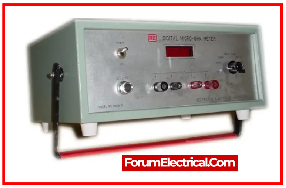
STEP-2: CONTACT RESISTANCE TEST
Test Equipment:
Micro-ohmmeter DLRO (or) T&R
- The joints and connections of the busway will be tested.
- Select which joints need to be examined.
- Ensure that the bolts are marked and that they have undergone a torque check.
- Verify that the current & voltage probes’ contact surfaces are dry and clean.
- Verify the cleanliness and dryness of the instrument probes.
- Ensure that the micro-ohmmeter is turned off while connecting.
- Set the micro-ohmmeter to zero.
- Assemble the voltage and current cables, making sure to match their polarities. The voltage cables should always be connected within the current wires.
- Turn the micro-ohmmeter ON.
- To reach the desired value, increase the current.
- Examine the resistance measurement.
- Compare measured values to the specifications provided by the manufacturer; compare the outcomes of various connections.
STEP-3: PHASING TEST
Test Equipment:
- Multimeter,
- Battery box (or) DV voltage source with multiple outputs
- The phasing test is used to ensure the busway phases continuity & the right phase sequence.
- To obtain total isolation of the main bus, disconnect all equipment linked to the busway, such as transformers & switchgear.
- Make sure the phases are not shorted together & are not connected to ground.
- Make that the phase identification labels match the main bus configuration and vendor drawings.
- Check that the phase sequence of the busway matches to the phase sequence of other associated equipment that includes switchgear & transformer.
- Attach the battery box at busway one end by doing the following:
- 0V to ground,
- 4.5V to phase A,
- 9V to phase B, and
- 13.5V to phase C
- Check the voltages for each phase at the busway other end with a multimeter.
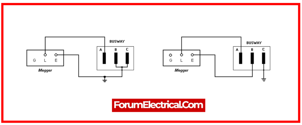
STEP-4: INSULATION RESISTANCE TEST
Test Equipment:
- Ohmmeter,
- Megohmmeter AVO,
- Thermometer,
- Humidity meter
- Take temperature and humidity readings and keep track of them.
- Each phase to ground & phase to phase insulation resistance of the busway should be measured.
- Disconnect the test busway from all other equipment & circuits.
- Make that the insulation boots, busway insulation, & bushings are clean and dust-free.
- Using an Ohmmeter, ensure that no electrical connection exists between the phases (or) between the phases and ground.
- Connect the megohmmeter’s line terminal to one phase of the busway & all other phases to ground and the megohmmeter’s earth terminal.
- Adjust the test voltage to the manufacturer’s recommended value.
- Measure the IR value – insulating resistance for one minute.
- Repeat for the remaining phases.
- Measure the insulating resistance between phases for one minute.
- Connect the megohmmeter’s line terminal to one phase of the busway & the earth terminal to another, with the remaining phase grounded.
- Repeat for the remaining phases.
- The measured insulation resistance (IR) values must be temperature adjusted and compared to the manufacturer’s values.
Formula for measuring Resistance (IR Test value)
The resistance levels and test voltages for insulation-resistance must match the manufacturer’s published specifications.
The numbers for the minimum resistance are based on a busway run of 1000 feet. For converting the measured resistance value to the nominal 1000-foot value, use the following formula:
R1000feet = [Measured Resistance x (Length of Run/1000)]
It is recommended to look at converted insulation resistance values that are lower than the manufacturer’s minimum. Testing for dielectric withstand voltage cannot start until insulation resistance has increased above minimum levels.
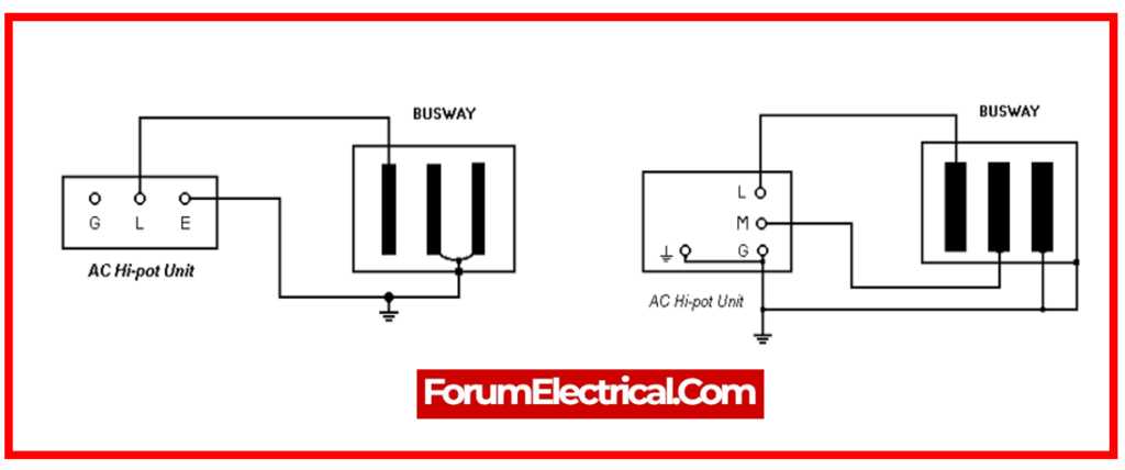
STEP-5: AC OVER POTENTIAL TEST
Test Equipment:
- AC Hi-Pot test set
- Thermometer
- Humidity meter
- Take temperature and humidity readings and keep track of them.
- Before executing the AC Hi-Pot test on the busway, the insulation resistance test is required to be effectively conducted.
- Because high voltage testing involves both high voltage & high energy, the test area must constantly be roped off with safety rope barriers.
- Only those directly involved in the testing process & fully aware of the risks entailed are permitted to enter the cordoned off area.
- Disconnect the test busway from all other equipment & circuits.
- Make that the insulation boots, busway insulation, & bushings are clean and dust-free.
- While conducting the over potential test between phase & ground, the test voltage must be provided from each phase to ground while the remaining phases are connected to ground.
- The Hi-Potronics AC Hi-Pot test set must be utilized to conduct the over potential test between phases.
- Before starting the test, make sure the hi-pot main switch is switched off & the voltage control switch is set to zero.
- Connect a suitable electrical ground to the hi-pot safety ground stud. Check sure the busway’s metal structure is attached to the ground.
- Connect the hi-pot test set’s line cable to the busway selected phase under test. Check that all connections are snug and have no sharp edges. The line cable must be kept short and supported along its length so that it does not come into contact with any grounded materials.
- Turn ON the hi-pot and set the required test voltage range. The test voltage should be set to the manufacturer’s guideline and applied for one minute.
- The AC Hi-Pot test has a “go or no go” outcome. The busway is judged to have passed the test if the Hi-Pot test voltage continues to exist for one minute without any breakdown of the busway insulation.