
- What is Busbar?
- What is the Purpose of a Busbar?
- What is Busbar Protection?
- How to Detect a Busbar Fault?
- Busbar Faults
- What are the faults of busbar?
- How Busbar Protection Works?
- Most Common Methods Used in Protection Schemes
- 1). Backup Protection
- 2). Differential Overcurrent Protection
- 3). Frame leakage Protection
- Busbar Protection Testing
- How do you test a busbar protection?
- Reverse Blocking/Interlocking Protection
- Busbar Protection Standards
What is Busbar?
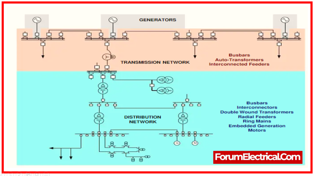
Electricity is collected from incoming feeders and distributed to outgoing feeders by an electrical bus bar. Thus, it is an electrical junction where all incoming and outgoing currents connect. Electric power is collected at the electrical bus bar.
Bus bar system includes isolator and circuit breaker. Upon fault, the circuit breaker trips and the faulty busbar unit is simply disconnected.
The electrical bus bar comes in circular, rectangular, cross-sectional, and other arrangements. Power systems generally use rectangular bus bars. Electrical bus bars are made of
- Copper and
- Aluminium.
What is the Purpose of a Busbar?
Electric power from entering feeders is sent to outgoing feeders through a busbar. The main function of a busbar is to distribute power. Busbars improve system efficiency.
What is Busbar Protection?
A metallic strip called a busbar is used to distribute high electrical power efficiently. It is kept within the enclosures of
- Switchgear,
- Panel boards, and
- Busways.
The primary function of a busbar is to gather electrical power from feeders & transmit it to feeders that are leaving. Electrical power is collected at one station (or) site.
The purpose of busbar protection, on the other end, is to shield (protect) the busbar against all electrical problems. A high electrical power system is the primary priority of the protective scheme.
A mechanical issue affecting all feeds to the busbar could result from any disruption in this type of system.
Typically, no protection is applied to the busbar. Although they are supposed to be dependable, they may malfunction and have an impact on the entire system if they were protected.
This post provides all the knowledge one needs to understand busbar protection methods, including how to identify defects (faults) and how they work.
How to Detect a Busbar Fault?
- Time-Delayed Distance Relay And
- Overcurrent Relay
were used years ago to detect busbar faults and clear them.
This method caused the defects to remain for a longer period of time. However, with the advancement of technology, currently have highly interconnected feeders with various line sections of varying lengths.
Time-delayed tripping for busbar failures is unacceptable in order to maintain system stability and minimize fault damage from high electrical faults.
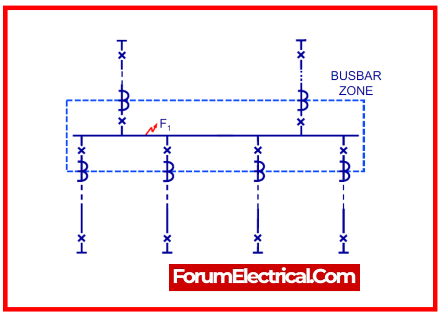
Consequently, it is simpler to find the defect in each unit form of the protective system or scheme while trying to identify a bus bar fault.
Busbar Faults
A busbar may experience a wide range of faults. These faults include deterioration of busbar material during installation, failure of the circuit breaker, foreign bodies that may have slipped on the busbar, mechanical damage due to earthquakes, failure of support by the insulator, resulting in an earth fault, & error during operation & maintenance, particularly in switchgear.
When a fault arises on the bus bars, the entire supply is cut off, and all healthy feeders are unplugged. The majority of the faults are single-phase in nature and only short-term.
All circuits connected to the defective area must be open in order to remove the bus fault.
What are the faults of busbar?
- Overvoltage causes support insulator flashover
- Polluted insulator causes overvoltage flashover
- Other linked equipment fails.
- Earthquake
- Mechanical damage
are the faults of busbar.
How Busbar Protection Works?
Differential relays are included in busbar protection methods through their operation.
A low differential relay (or) a high impedance differential relay could be the type of relay.
When employed, high impedance busbar protection is another name for high differential relays and similarly to low impedance busbar protection, which is another name for low deferential relay. Fast, dependable, and steady busbar protection is required.
Most Common Methods Used in Protection Schemes
The bus zone protection schemes that are most frequently used include:
- Backup Protection
- Differential Overcurrent Protection
- Circulating current protection
- Voltage Overvoltage Protection
- Frame leakage Protection
- Single Busbar Frame-Earth Protection
- Sectioned Busbar Protection
- Double Bus Substation
1). Backup Protection
This is the simplest way of shielding the bus-bar from faults. The supplying system is the cause of the bus-bar fault. Thus, the supply system is protected by backup.
The primary purpose of such a system is to protect the transmission lines. However, because the protective system is so reasonable, bus-bar protection is also an application for it.
There are numerous disadvantages to the backup protection system, such as delayed activation and the need to disconnect multiple circuits for multiple transmission line requirements.
One of the bus-bar protection system’s small disadvantages is its slow protective mechanism.
2). Differential Overcurrent Protection
There are more options to implementing these principles in this differential protection scheme, which are as follows:
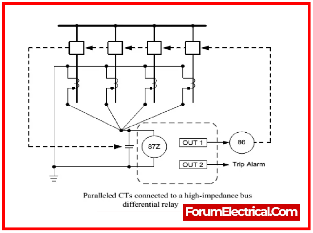
High Impedance Differential Protection Scheme
Because of its great resilience, rapidity, and protected functionality, this method has been in use for long time. The mechanism here employs voltage throughout the differential junction nodes.
The disadvantage of this type is that it requires concentrated CTs and is very expensive. During the busbar damage, an additional voltage regulating resistor is required for energy absorption.
Low Impedance Differential Protection Scheme
This method does not require any CTs. It is capable of withstanding significant CT overload in the event of external damage. This system also provides a wide range of tripping speeds. Because of its advanced algorithms for differential protecting steps, the implementation of microprocessor-dependent relays will increase usage.
A). Current Differential Protection
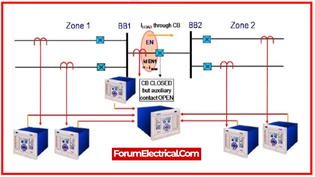
A key component of the busbar protection mechanism is Kirchhoff’s current law, the current differential protection method is based on it, which states that the current entering the bus-bar equals the current leaving the bus-bar.
The total of the incoming & outgoing junctions is zero.
If the sum of currents is not equivalent to zero, the system has a malfunction.
The differential protection technique is used to protect against both phase-to-phase and ground faults.
Current transformers are installed on both the incoming & outgoing ends of the bus-bar. The secondary terminals of the CT-current transformer are connected in parallel.
The current transformer’s summing current flows through the relay’s working coil. The current flowing through the relay coils shows the presence of a short circuit current on the CTs’ secondary.
As a result, the relay transmits a signal to the circuit breakers, causing the contacts to open.
The disadvantage of such schemes is that the iron cored current transformer leads the relay to fail when there is an external fault.
Small switchgear systems do not use this protection method.
B). Voltage Overvoltage Protection
This method makes use of coreless CTs. The secondary sides of the CTs have more turns thanks to the usage of linear couplers. With the assistance of the pilot wires, the secondary relays were connected in series. Additionally, the relay coil and the second terminal are connected in series.
The total secondary current of the CTs drops to zero when the system is error-free or an external fault arises. The differential relay receives the fault current when an internal fault occurs. When the relay activates, it instructs the circuit breaker to open its contacts. Therefore, shielding the system from danger.
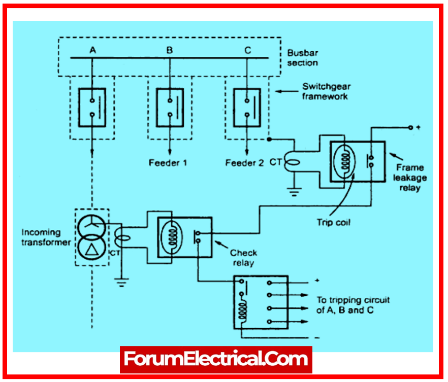
3). Frame leakage Protection
This method provides a single ground tank connection over a CT that feeds an overcurrent relay, connects all of the framework, circuit breakers, tanks, and other components, and insulates the bus-supporting structure & associated switchgear from the ground. Every circuit connected to the bus has its breakers tripped by a multi-contact auxiliary relay that is managed by the overcurrent relay.
With this kind of protection, an overcurrent relay is connected to the secondary of a CT, which grounds the only metal supporting structure (or) fault-bus.
The relay is not operational during normal operation; nevertheless, in the event of a failure involving an electrical connection between a conductor & the ground supporting structure, current will flow via the fault bus and into the ground, activating the relay.
All of the breakers that connect the equipment to the bus will trip as a result of the relay operating.
There are three different types of frame leakage protection schemes:
- Single Busbar Frame-Earth Protection
- Sectioned Busbar Protection
- Double Bus Substation
A). Single Busbar Frame-Earth Protection
This scheme is used to calculate the currents flowing from the switchgear to earth frame in the occurrence of an earth fault. This method is set up so that the current recognized by CT, which is put on the earthing conductor, stimulates the immediate relay as shown in the picture. Here, it’s essential to use concrete as the foundation to protect the switchgear from the earth.
B). Sectioned Busbar Protection
The busbar system as a whole is divided into two sections here, and each section is likewise protected. This can be accomplished by cutting each shape into sections and adding an earth conductor to each component. Additionally, each part has a CT and a protective relay of its own.
The protective relay in this arrangement is designed to trip when internal damage occurs to the associated portion, leaving the other section undisturbed.

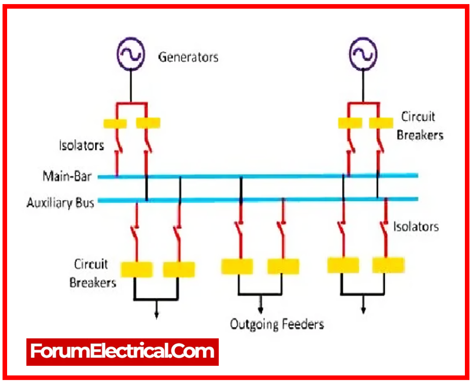
C). Double Bus Substation
Bus-bar protection is applied to the entire bus in this case, and additional trip systems are connected to its primary bus. In order to protect the components from operations which occurred from functionality due to either mechanical (or) human shocks, a safety system is used. Minimal component systems are not appropriate for this safety system.
The safety system must prevent the functionality that results from current flowing to the ground through the switchgear frame when damage is caused by low voltage wire. By applying the neutral current to stimulate the relay, the functionality is supplied.
The frame earth relays will activate after a certain amount of time if the neutral current safety system is inactive.
Busbar Protection Testing
The busbar protection is tested using a current source. It is used to do differential busbar relay testing.
The busbar relay, like the standard differential relay, should be subjected to a stability test. This is the busbar protection testing.
How do you test a busbar protection?
- High Potential (or) Hi-Pot Test,
- Partial Discharge Test,
- Insulation Resistance Test (Megger Test),
are three of the most essential tests that are carried out on the busbar protection.
Reverse Blocking/Interlocking Protection
Time delay upstream relays are used in conventional protection systems to eliminate damage as it occurs. This busbar locking method can be used to protect the distribution system from a single source by employing a numerical algorithm. In this case, time grading is required to prevent defective circumstances by synchronizing the overcurrent relays.
The primary advantages of employing this method are:
- These systems are easily adaptable to the expansion of substations.
- By comparison, this method requires less money than the differential protecting technique.
- This method offers a faster damage resolution mechanism than others that rely on upstream feeder safeguarding-caused trips. Zone sequence interlocking schemes is another name for these.
These are the primary methods of protecting busbars. The definition of busbar protection, different kinds of protection schemes, & busbar testing procedures are all explained in the post.
Busbar Protection Standards
Busbar protection is essential for assuring power system dependability and safety. The design, installation, & operation of the busbar protection systems are governed by a number of standards. Among the commonly accepted standards are:
- IEC 61850: This standard is concerned with communication networks and power utility automation systems. It specifies communication protocols for substation automation, particularly busbar protection.
- IEC 60255: This standard establishes the performance and testing requirements for protective relays. It discusses different features of power system protection relays, particularly those used for busbar protection.
- IEEE C37.230: This IEEE standard addresses the specifications for protective relays utilized in electrical power systems. It incorporates busbar protection plan guidelines.
- IEEE C37.234-2009: A specific IEEE standard that addresses protective relays and bus and line protection methods.
- ANSI/IEEE C37.234: This standard specifies protective relaying for utility and industrial systems. It addresses busbar protection in substations.
- IEC 61869: This standard describes instrument transformers, particularly current transformers utilized in busbar protection schemes.
