
A variety of different testing processes need to be carried out on an electrical power transformer before the device can have its specifications and performance levels validated. Before a transformer is sent out to a customer, it goes through a series of testing at the facility where it was manufactured.
There are two primary kinds of testing that are carried out on transformers by their manufacturers:
- The type test of transformer and
- The routine test of transformer.
Certain transformer tests additionally occur at the customer site before the device is put into service. These tests may be performed on a periodic, regular, or emergency basis during the device’s lifetime of operation.
Transformers reduce the high-voltage energy produced by power plants to the voltage required by electrical equipment in residences, buildings, industrial facilities, and other structures. Transformers may be tested using several different techniques. Some fundamental tests have been provided in this post.
Why is testing a transformer very necessary?
- To determine whether the primary elements that comprise off electrical transformers are functioning appropriately.
- To ensure that the transformer in its whole is operating properly.
- To minimise the possibility of transformer not operating properly.
- For the purpose of verifying the transformer’s specs and its performance.
Different types of Transformer Testing
Test carried out in industry
1). Type Test
2). Routine Test and
3). Special Test
Test carried out in location
1). Pre-commissioning test
2). Condition Monitor/ Periodic test and
3).Emergency test
Test carried out in industry
1). Type Test
Transformer type tests are used to determine if the transformer has been engineered in accordance with the customer’s expectations and design requirements. The transformer must thus undergo this kind of testing throughout the production process. The transformer must undergo some kind of testing to verify the Customer’s design requirements. These tests are carried out in a production batch or a single prototype unit. The fundamental design of a transformer in a manufacturing lot is validated and confirmed by the transformer type test.
Measurements of the transformer’s many specifications are part of the type testing. It includes,
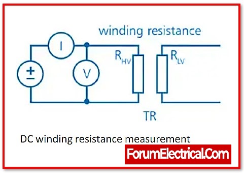
- Transformer winding resistance measurement
- Transformer turns ratio testing
- Transformer vector group testing
- measuring a transformer’s impedance voltage
- measuring a transformer’s short circuit impedance
- measuring the transformer’s load loss (including a short circuit test)
- Measurement of a transformer’s no-load loss & current (including open-circuit test)
- Transformer insulation resistance measurement
- testing for dielectrics
- testing the transformer’s temperature increase
- Tests for no-load tap changers
- tests for vacuum on radiators and tanks
2). Routine Test
Routine tests are performed on the transformer in a manufacturing batch to assess and validate its operating performance.These tests must to be carriedout on each production unit.Except for the temperature increase(rise) test and the vacuum test, all tests are included in this list.It includes,
- Transformer winding resistance measurementTransformer turns ratio testing
- Transformer vector group testing
- Measuring a transformer’s impedance voltage
- Measuring a transformer’s short circuit impedance
- Measuring the transformer’s load loss (including a short circuit test)
- Measurement of a transformer’s noload loss & current (including open-circuit test)
- Transformer insulation resistance measurement
- Tests for no-load tap changers
- Testing the transformer’s oil pressure to look for leaks at joints & gaskets.
3). Special Test
To provide the user valuable information, special tests are carried out. These tests are conducted as part of the transformer’s maintenance and operation.
The following are a few of the unique tests conducted during the transformer’s maintenance:
- Transformer dielectric testing.
- Transformer short-circuit test.
- Measuring the transformer’s three-phase and zero-sequence impedance
- Determining the measurement’s acoustic noise level.
- Harmonic analysis of the transformer’s no-load current.
- Calculating the power consumption of the circuit’s oil pumps & fans.
- Measurement of a few circuit components, such as the Buchholz relay, pressure relief mechanisms, oil preservation systems, temperature indicators, & many more.
Test carried out in location
1). Pre-commissioning test
Transformer pre-commissioning tests consist of,
- Operational inspection of the defence mechanism.
- Measurement of insulation resistance (IR).
- Bushings on capacitors are measured.
- Voltage ratio (or turns ratio) measurement.
- Measurement of the transformer’s polarity or vector group.
- Measuring the resistance of winding.
- Measurement of transformer vibration.
- The transformer’s magnetic balance is tested.
- A measure of the transformer’s frequency balance response (FRA).
- Floating neutral point measurement.
- The transformer’s magnetising current and short-circuit impedance are measured.
- Operational evaluation of the OLTC’s (On-Load Tap Changer).
- Measurement of the transformer’s REF (Restricted Earth Fault) and differential’s stability.
- Measuring bushing current transformers (BCT’s).
2). Condition Monitor/ Periodic test
These tests are performed on a regular basis to evaluate the transformer’s performance and condition. Periodically, the transformer’s condition is examined to see if it satisfies customer needs. On a regular basis, such as once a week, once a month, and once a year, these tests are conducted on the location after the functioning of the transformer. The kind of transformer being utilised determines the transformers’ routine maintenance schedules.
By routinely checking the functioning of the transformer, these tests facilitate in the early detection of defects.
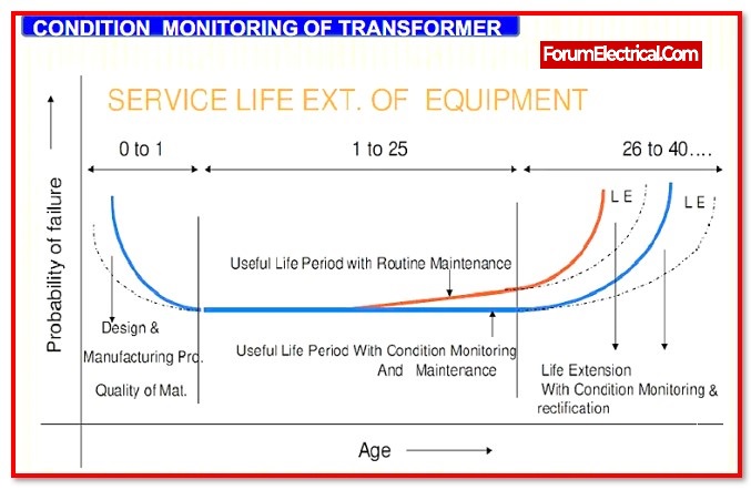
Ex:If the result of the transformer’s insulation resistance measurement is lower than usual, it indicates that the fault is still in its early stages.
3).Emergency test
These tests are performed at the location to check for any problems or damage that may have occurred to the transformer while it was being used.
Ex: A measurement of high temperature even if the ventilators are operating effectively; this measurement also comprises a measurement of the resistance in the windings and an examination of the oil that is utilised for the cooling (reduces heat and insulation) of the transformer.
Other Types of Transformer Test
Other types of transformer’s testing are,
1). Turns Ratio Testing
Transformer turns ratio testing is often performed to confirm that the winding ratio among the primary & secondary coils is within specified parameters. This method of transformer testing also assures that the transformer will either deliver step-up (or) step-down voltage. A step-down transformer with 100 primary turns & 10 secondary turns, for example, will drop the voltage by a factor of 10 – matching to the secondary coil – as well as doubling the current by 10.

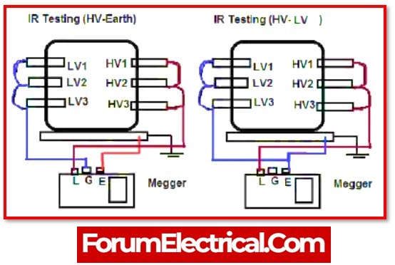
2). Insulation Resistance Testing
The Megger test, commonly known as insulation resistance testing, is used to verify the standard of insulation inside the transformer itself. These tests are carried out using a megohmmeter, type of the required transformer test devices that functions similarly to a multi-meter. To successfully complete the test, the insulation of a transformer must be proven to be more resistant than the resistance established by international norms (international standards ) for that transformer type. If it measurements any lower, it might indicate a problem with the insulation, which may need replacement.
3). Power Factor Testing
Power factor testing is the method of determining the power loss of an insulating system by measuring the angle of the resultant current of power that happens when an alternating current voltage is applied. The current angle must be at 90° for the test outcomes to be most effective; however, insulation is seldom perfect. The closer the current is to the angle of 90°, the greater the insulation.
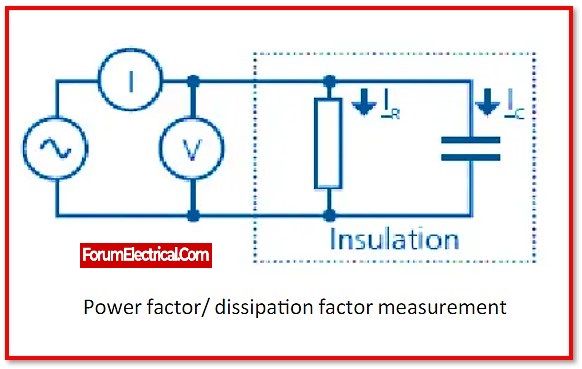
This test is conducted using a power factor test kit and may be repeated as needed during the transformer’s life. This may assist identify deteriorated or faulty insulation over time & predict when the transformer should be replaced.
4). Resistance Testing
This transformer testing is performed after a transformer has been allowed to settle to the temperature of the air surrounding it. This is done to examine for any discrepancies between the transformer’s openings and windings. This helps to confirm that all of the circuits remain properly wired and linked. An ohmmeter is used for this test.
5). On Load Tap Changing Test
In certain applications, a transformer’s output voltage must change depending on the application. A transformer, in basic terms, provides a set output voltage based on the accessible input. However, there is a specific type known as an auto transformer.
Considering a single winding that starts at A (main) and ends at B (secondary). In the middle, there is a C tap position. This tap may be moved.
The number of turns between A & B is referred to as the primary winding, whereas the number of turns between B & C is referred to as secondary winding. Because position C is variable, the voltage across the secondary windings varies. This is known as an autotransformer.
As a result, a test known as on-load tap change is done on these types of devices to assess how they function in the face of different workloads. The circuit has a set number of taps (tapping), with a center tap that serves as an indicator for the number of turns.
The center tap will be adjusted and placed on a certain tap position to establish the turns ratio, and the output voltage will be tested appropriately.
6). Dielectric Test
This test is a continuation of the insulating resistance test. It is used to test the insulation strength of the transformer.
It is accomplished through the use of two tests:
- A separate source voltage withstand test and
- An induced voltage test.
In the first test, the applied voltage is applied to one winding for 60 seconds. The earth is linked to the second winding.
If the dielectric characteristics are not correct, insulation loss can occur during this test, and leakage current may be seen.
In the second test, the main winding is left open while the secondary winding is subjected to voltages that are twice as amplitude and frequency as the rated voltage.
For 60 seconds, this voltage will be administered. If no breakdown or leakage occurs after such a full load test, the insulation is adequate.
7).Magnetising Current Test
A transformer magnetising current test is conducted to identify faults in the magnetic core, shifting windings, failure in inter turn insulation, or an issue with tap changers. These factors alter the magnetic circuit’s effective reluctance, influencing the current needed to create flux in the core.
Maintain the tap changer in the lowest position & open all HV & LV terminals. Then, for three-phase transformers, apply a three-phase 415 V supply to the line terminals and a single-phase 230 V supply to the single-phase transformers.
Take measurements of the supply voltage & current in each phase.
Repeat the magnetising current transformer test while maintaining the tap changer in the usual position.
Repeat the experiment while maintaining the tap at the highest position.
In the case of three phase transformers, there are normally two comparable higher readings on two outside limb phases on the transformer core & one lower reading on the centre limb phase.
Within 30% of acceptable consistency of the measured exciting current with the preceding test is typically regarded. If the detected exciting current value is 50 times more than the value obtained during factory testing, there is a possibility of a winding issue that requires further testing.
Caution: Before measuring DC resistance, do this magnetising current test on a transformer.
8). Vector Group Test
A vector group test of the transformer is required in a three-phase transformer. Proper vector grouping is a critical requirement for parallel transformer functioning.

There are many internal connectors for three-phase transformers. These multiple connections provide varying magnitudes and phases of the secondary voltage; the magnitude may be corrected for parallel operation by selecting an appropriate turn ratio, but the phase divergence can’t be rectified.
As a result, users must choose a transformer suited for parallel operation, with the same phase sequence & phase divergence. The phase sequence & phase divergence between primary & secondary are the same in all transformers with the same vector ground.
Before purchasing an electrical power transformer, users should confirm that the transformer’s vector group is compatible with his or her existing system. The transformer’s vector group test validates user needs.
9). Temperature Rise Test
This test is carried out on oil transformers in order to determine both the temperature of the oil and the temperature of the windings. It is required to fall inside the parameters that have been set.
When it is time to put a transformer into operation, standard tests are carried out on it to ensure that it will function properly and perform adequately under any and all of the operating circumstances.
10). Induced Voltage Test
The transformer’s induced voltage test is intended to inspect the line ends, inter-turn insulation, main insulation to the ground and insulation between the windings.
- Maintain an open circuit in the transformer’s primary winding.
- Supply the secondary winding with three-phase voltage. The applied voltage must be two times as strong and as often as the secondary winding’s rated voltage.
- The test must be completed in 60 seconds.
- A voltage that is less than one-third of the complete test voltage must be used to begin the test, and it must be raised to the desired measured value.
If there isn’t a breakdown while the test is running at its maximum voltage, the test is successful.
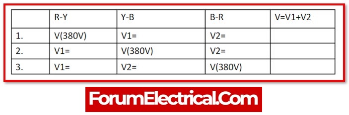
11). Magnetic Balance Test
Only three-phase transformers are subjected to a magnetic balance test to determine if the magnetic circuit is unbalanced.
- Maintain the transformer’s tap changer in its default position.
- Now detach the neutral of the transformer from the ground.
- Next, connect a single phase, 230 V AC supply to the neutral terminal and to one of the HV winding connections.
- Measure the voltage in the neutral terminal and the other two HV terminals.
- For each one of the three stages, repeat the testing process.
A magnetic balancing test of the transformer should be performed again for the LV winding in the case of an autotransformer.
The transformer’s core has three limbs arranged side by side. One limb is used to wind a single phase. The location of the limb inside the core affects the voltage generated in each phase.
Frequently asked Questions
1). Why are transformer tests necessary?
To examine or validate the transformer’s performance and specifications in regards to the needs of the user.
2). How should the transformer be maintained?
By examining the transformer’s oil leaks, maintenance may be performed on the transformer.
- Dust, sludge, and grime may be taken out using the filtering process.
- On both sides of the windings, loose connections should be periodically checked for.
- To prevent cracking, bushings should be carefully cleaned.
- The examination of dissolved gases should be done often.
3). What does the measurement of insulation resistance in transformers have?
The insulation resistance (IR) between the primary & secondary windings (HV and LV) in relation to earth must be measured.
4). What does measuring winding resistance provide?
This test is used to confirm that the resistance of each phase matches the values specified in the design. It gauges the main and secondary windings’ resistance.
5).Which relay type is implemented in transformer protection?
The transformer is protected by a Buchholz Relay from internal damages such short circuits, winding problems, insulation failures, etc.
Conclusion
Without any of these tests, the functioning of the transformer might be significantly hampered, which is a major risk as the reliability of the transformer must be preserved at all costs.
