
Ensuring proper earthing is one of the most important factor to check in transformer maintenance and commissioning.
An Earth Continuity Test verifies that all exposed metallic parts of the transformer are effectively bonded to the primary earth terminal that is providing a reliable, low-impedance path for fault currents & minimizing electrical hazards to both personnel & equipment.
- Purpose
- Importance of Earth Continuity Testing
- Test Points Covered
- Equipment Required
- Safety Precautions
- Step-by-Step Test Procedure
- Step 1: Instrument Verification
- Step 2: Identify the Main Earth Terminal
- Step 3: Connect Reference Probe
- Step 4: Test Each Point (Source)
- Step 5: Documentation
- Acceptance Criteria
- Test Results: Example Checklist
- Result Interpretation & Remedial Actions
- Documentation and Reporting
- When to Perform the Earth Continuity Test?
- Conclusion
A transformer is a high-voltage (HV) equipment and any failure in its earthing system can result in dangerous touch voltages on the accessible metal surfaces during a fault condition.
Such conditions pose a severe risks of
- Electrocution,
- Equipment damage and
- Fire.
Therefore earth continuity testing is not a regular checklist but a mandatory safety requirement mandated by international standards including IEC 60076, IEEE C57 series and national electrical safety codes.
This post give a comprehensive guide to performing the Earth Continuity Test on power transformers that covering the purpose of each test point, required instruments, step by step procedure, acceptance criteria, result interpretation & documentation best practices.
Purpose
The primary objectives of the Earth Continuity Test are
Prevent the dangerous touch potentials on the metallic surfaces during fault conditions.
Ensure a fast operation of the protective devices (fuses, relays, circuit breakers) by providing a low impedance fault return path.
Meet requirements of IEC 60364, IEC 60076, IEEE 80 and local electrical codes.
Confirm a structural integrity of bonding conductors & earth connections over the transformers service life.
Validate that all the metallic parts disturbed during maintenance are properly reconnected to the earth system.

Importance of Earth Continuity Testing
A high resistance at any earth bonding point indicates a
- Loose connection,
- Corroded joint,
- Broken conductor,
- Paint film isolating the metal surface.
Identifying and rectifying such defects before energisation prevents catastrophic failures.
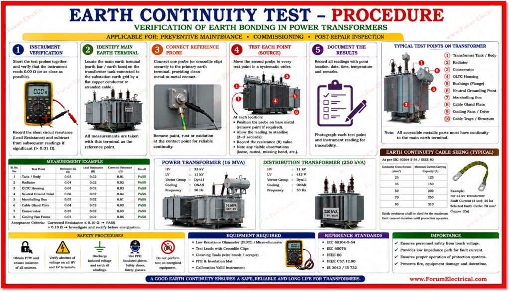
Test Points Covered
The Earth Continuity Test should be conducted at all accessible metallic parts of the transformer.
The following are the standard test points:
| Test Point | Component Description | Significance |
|---|---|---|
| Transformer Tank / Body | Main outer steel enclosure | Largest metallic mass and should be solidly earthed. |
| Radiator | Cooling fins / radiator bank | Often bolted separately and bonding can loosen. |
| Neutral Grounding Point | LV neutral terminal / NGR | Essential for the system neutral stability & protection. |
| Marshalling Box | Control wiring enclosure | Personnel safety during relay / CT inspection |
| Cable Gland Plate | Entry plate for LV (Low Voltage) cables | Bonding ensures cable armouring is earthed |
| Other Metallic Parts | Conservator, OLTC housing, bushing flanges, cooling fans & cable trays | Any accessible metal must have continuity to earth |
Equipment Required
- Digital Multimeter (DMM) with Continuity / Resistance mode capable of reading down to 0.01 Ω
- Low-Resistance Ohmmeter (DLRO / micro-ohmmeter) for accurate measurements below 0.1 Ω
- Test leads with crocodile clips (minimum 1.5 m length rated for the test voltage)
- Personal Protective Equipment (PPE): insulated gloves (Class 00 minimum), safety glasses & arc flash rated clothing
- Isolation and earthing permit (Permit to Work / Lockout-Tagout documentation)
- Test record sheets (or) digital test management software
- Calibration certificates for all test instruments
Safety Precautions
Earth continuity testing should only be performed on a fully isolated, de-energised transformer.
Strict observance of the following precautions is mandatory.
- Obtain a signed Permit to Work (PTW) / Isolation Certificate before the process of commencing.
- Use an approved voltage indicator to confirm the isolation of all HV and LV terminals.
- Site safety requires earthing and short-circuiting HV and LV leads.
- Ensure no induced voltages are present from nearby live equipment.
- Inspect all test leads for damage and replace if insulation is cracked (or) bare conductors are exposed.
- Never perform continuity testing on an energised equipment under any conditions.
Step-by-Step Test Procedure
Step 1: Instrument Verification
Before starting, short the test probes together & verify that the instrument reads 0.00 Ω (or as close as possible).
Record the short circuit resistance as the instrument lead resistance which should be subtracted from the subsequent readings if significant (typically >0.01 Ω).
Step 2: Identify the Main Earth Terminal
Locate the main earth terminal (earth bar / earth boss) on the transformer typically a dedicated earthing lug on the tank wall, that is connected to the substation earth grid by a flat copper earth conductor (or) stranded cable.
All measurements are taken with this terminal as their reference point.
Step 3: Connect Reference Probe
Connect one probe (or crocodile clip) securely to the primary earth terminal, providing a clean metal-to-metal contact.
To have a reliable electrical connection and continuity remove any paint (or surface oxidation) at the contact point.
Step 4: Test Each Point (Source)
Move the second probe (2nd probe) to every test site in a systematic order.
At each location:
- Position the probe directly on bare metal (remove paint if required with a wire brush / scraper).
- Allow the reading to stabilise (typically 2 – 3 seconds).
- Record the resistance (IR) value in the test record.
- Make a note of any visible observations (visual inspection) such as rusted connections, missing of bonding links & broken conductors.
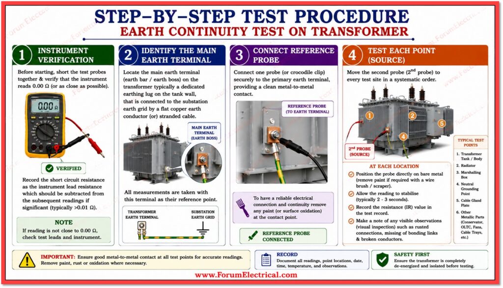
Step 5: Documentation
Complete all the test record for each point immediately.
Photographs of each test point & the instrument reading are recommended as supporting evidence for the test report.
Acceptance Criteria
The following criteria apply to all earth continuity measurements.
| Parameter | Acceptance Limit | Remarks |
|---|---|---|
| Continuity | should be present at ALL test points | Open circuit = FAIL and analyze immediately |
| Maximum Resistance | < 1.0 Ω | Absolute upper limit per IEC / IEEE standards |
| Preferred Resistance | < 0.1 Ω (ideally ≈ 0 Ω) | Indicates solid and low-impedance bonding |
| Warning Zone | 0.1 Ω – 1.0 Ω | Investigate and remediate before energisation |
| Fail | > 1.0 Ω or open circuit | Do NOT energise and rectify bonding fault |
Note
Some standards specify even tighter limits (e.g., < 0.5 Ω) for the specific transformer ratings (or) installation categories.
Always refer to the project specification & applicable national standard.
Test Results: Example Checklist
In the test documented below all readings were below 0.1 Ω confirming a reliable earth connection & satisfactory bonding via the transformer structure.
| Test Point | Reading (Ω) | Acceptance Limit | Result |
|---|---|---|---|
| Transformer Tank / Body | 0.02 Ω | < 1.0 Ω | PASS ✔ |
| Radiator | 0.05 Ω | < 1.0 Ω | PASS ✔ |
| Neutral Grounding Point | 0.03 Ω | < 1.0 Ω | PASS ✔ |
| Marshalling Box | 0.07 Ω | < 1.0 Ω | PASS ✔ |
| Cable Gland Plate | 0.04 Ω | < 1.0 Ω | PASS ✔ |
| Conservator Tank | 0.06 Ω | < 1.0 Ω | PASS ✔ |
| OLTC Housing | 0.08 Ω | < 1.0 Ω | PASS ✔ |
| Cooling Fan Assembly | 0.09 Ω | < 1.0 Ω | PASS ✔ |
Result Interpretation & Remedial Actions
All test results should be carefully interpreted in the context of the transformer rating, installation conditions and applicable standards:
- Readings at (or) near 0 Ω: Excellent bonding. No action required.
- Readings of 0.1 Ω to 0.5 Ω: Acceptable but the trending towards degradation. Clean connection surfaces, re-torque bonding conductors and retest.
- Readings of 0.5 Ω to 1.0 Ω: Warning & Investigate cause. Check for corroded joints, loose nuts/bolts, missing bonding links (or) paint films. Remediate & retest before energisation.
- Readings above 1.0 Ω or open circuit: FAIL. Do not energise the transformer. Locate & repair the broken (or) high-resistance earth path. Retest after repair.
The common causes of high earth resistance include corrosion at the bolted connections, inadequate conductor cross-section, mechanical damage to bonding conductors and paint (or) oxide film at contact interfaces.
Documentation and Reporting
The comprehensive documentation is essential for quality assurance, regulatory compliance & future maintenance reference.
Each test report should include:
- Transformer identification: Rating, serial number, location, circuit reference.
- Date, time and ambient temperature at time of testing.
- Instrument details: Make, model, serial number and calibration due date.
- Full table of test results.
- Pass / Fail determination for each point & overall verdict.
- Photographs of each test point & instrument reading.
- Name, qualification and signature of the test engineer.
- Reference to the applicable standard (IEC 60076, IEEE C57, project specification)
When to Perform the Earth Continuity Test?
The Earth Continuity Test must be conducted at the following stages:
- Commissioning: Before the first energization of a new (or) relocated transformer.
- Preventive Maintenance: Typically annually maintenance is required as specified by the maintenance schedule.
- Post-Repair Inspection: After any major maintenance activity involving tank opening, bushing replacement, OLTC overhaul (or) cable gland work.
- After Mechanical Damage: Following any impact, flooding (or) seismic event affecting the transformer installation.
- Post-Outage Inspection: After prolonged outage where environmental degradation can have affected bonding connections.
Conclusion
The Transformer Earth Continuity Test is a simple but essential test for power transformer electrical safety.
For people safety, equipment protection & fault protection system operation, all metallic parts require a continuous, low-resistance link back to the primary earth terminal.
As detailed in the sample data consistent readings below 0.1 Ω (< 0.1 Ω) indicate reliable and proper earthing in the transformer assembly.
Transformers are safe to energize & reliable throughout their operational life because to rigorous testing, detailed documentation and rapid correction of defects.
Avoid to skip this essential test during commissioning, preventive maintenance (or) post-repair inspections.
A properly earthed transformer improves system reliability, personnel safety and equipment protection.