
Installation of a Variable Frequency Drive (VFD) is a significant undertaking that necessitates great attention to detail to ensure the safety, efficiency, and best performance of the motor-driven applications.
- Preparations & Planning
- Pre-Installation Checks
- Installation Checks
- Installation Procedure
- Enivronmental Condition
- Earth & Control Cables
- EMC (Electromagnetic Compatibility) – Correct Wiring
- Input Protection & PF Capacitors
- VFD Configuration
- VFD Startup
- Energy Savings
- Testing & Commissioning
- Document & Compliance
- Standards & Regulation
- Safety & Maintenance
- Summary
If you are an experienced professional or are installing a VFD for the first time, the thorough guidelines below will help you ensure a successful installation.
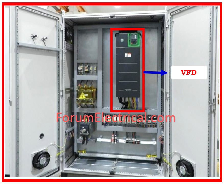
When you acquire a new VFD for the control system, the next step is to install it.
To ensure optimal performance, there are a few important points to consider during the VFD installation procedure.
In this post, we are going to demonstrate you how to install VFD.
Preparations & Planning
Before you start any installation, ensure that you have the suitable VFD model for your application’s power & motor needs.
A thorough comprehension of the VFD’s characteristics and limits is required, therefore spend time to reading the manufacturer’s handbook carefully.
Pre-Installation Checks
- Verify that the VFD model received matches the one ordered.
- Ensure that the input supply, VFD, and motor voltages are all the same.
- Ensure that the VFD rated current is greater than (or) equal to total full load current of all motors being driven simultaneously.
- If a disconnect (or contactor) is utilized between the VFD & motor, it must be interlocked with the VFD start instruction.
- Otherwise, the VFD may trip when the disconnect is closed while in RUN mode.
- There are no power factor capacitors put between the VFD and motor.
- Cable distance connecting VFD & motor meets VFD specifications.
- Ensure input & motor power cables match VFD terminal dimensions.
- Multimotor applications include individual motor protection.
Installation Checks
Environment
- Ambient Temperature
- IP Category
- Clearances for mounting
- Cooling & VFD heat loss.
- Harmonics
Drive Connections
- Earthing
- Control and power cable layout,
- EMC-correct wiring, input protection, and
- Power factor correction capacitors.
Drive Configuration
- Configure the drive and apply application-specific parameters.
Startup
- During startup, ensure a balanced voltage and proper motor direction.
Installation Procedure
Enivronmental Condition
- VFDs in supply have an operating temperature range of 40-50 degrees Celsius. If the VFD’s ambient exceeds the standards, derating must be considered.
- Correct ambient temperature prevents the VFD from overheating.
- VFD IP categories include IP00, IP20, IP21, IP54, and IP66. Choose a place for installing the VFD based on the IP.
- IP00 VFDs can be put in panels, whereas IP66 VFDs are recommended for water splash conditions.
- The VFD handbook provides clearance requirements for the sides, top, and bottom. Follow that steps.
- Failure to follow that step can obstruct the natural flow of airflow, causing the VFD to overheat.
- The environment must be free of corrosive gasses and dust.
- Determine the total heat loss from installed VFDs and make necessary cooling arrangements to maintain the required ambient temperature.
- If a large number of VFDs with high power ratings are installed in the same area, having supply and return air ducts directly linked to the VFD (or panel) might assist reduce the amount of air conditioning capacity required.
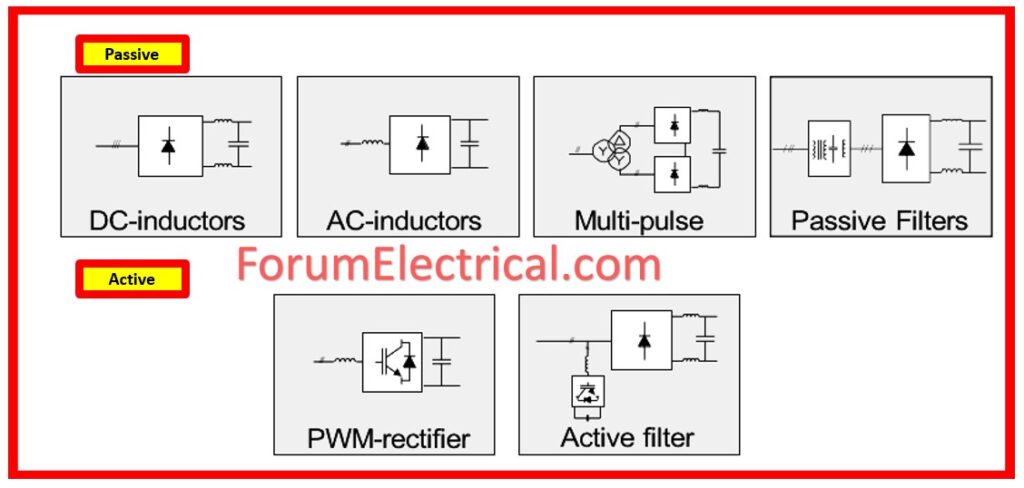
- Connecting a VFD input supply to several power electronic equipment may result in a high level of harmonics.
- To minimize harmonics in the system, use one of the following procedures.
Earth & Control Cables
- Ensure earth connections are properly secured. VFDs have a large leakage current & must be properly earthed for safety purposes.
- Control & communication cables must be insulated.
EMC (Electromagnetic Compatibility) – Correct Wiring
- Use screened/armoured motor and control cables.
- Installation in rigid metal conduits does not require screened cable, however the motor cable should be installed separately from the control & primary cables.
- Connect screen/armour/conduit to ground at both ends for motor and control cables.
- Do not end the armour with twisted ends. It raises the screen’s high frequency impedance, reducing its effectiveness at higher frequencies.
- Do not use unscreened or unarmoured motor (or) control cables within VFD cabinets.
Input Protection & PF Capacitors
- Use input disconnect, SFU, MCCB, and semiconductor fuses.
- Fuses should match the I2t rating of the rectifiers used in the VFD input section, thus utilize the correct fuse type and rating.
- To operate PF Correction systems successfully in harmonic conditions, resonance issues must be addressed.
- Detune the system from its resonant frequencies, which can be accomplished by connecting detuning reactors in the series with capacitors.
VFD Configuration
- Set parameters.
- Setting the necessary parameters for the needed application is essential to a smooth launch (commissioning).
The minimum parameter settings are:
- Motor data, ramp up/down time, and torque characteristics.
- Primary voltage
- Network address and baud rate
- Frequency reference (max/min)
- Configure digital and analog IO.
VFD Startup
- Check balanced output voltages & motor rotation direction after powering up and starting the VFD.
Energy Savings
Regenerative vs Dynamic braking
- If the load is regenerative, choose a regenerative scheme (only relevant if VFD selection is not yet completed).
Where are Sensors Installed?
- For retrofits, keep dampers & throttling valves open.
- Utilize squirrel cage motors rather than slipring motors.
Testing & Commissioning
- Once the VFD has been installed and configured, run thorough testing without load to ensure correct operation.
- Subsequent load tests will confirm the system’s performance under operational conditions.
- This step is essential for ensuring that everything is properly set up before beginning full-scale operations.
Document & Compliance
- Keep thorough documentation of all installation procedures, configurations, and tests.
- Keep the VFD handbook and associated schematics as a portion of your operational records.
- Ensure that your installation meets all applicable regulations and standards.
Standards & Regulation
- IEC 61800-3: EMC requirements for VFD systems (conducted/radiated emissions & immunity).
- IEC 60034-17 / IEC 60034-25: Motors Supplied by VFDs – Focuses on motor design and insulation suitable for use with VFD output.
- IEEE 519: Harmonic Control in Electrical Power Systems – Specifies limits for harmonic distortion caused by VFDs on power supply systems.
Safety & Maintenance
Regular inspections & maintenance are essential for ensuring the VFD’s functionality and safety.
Stick to the manufacturer’s recommended schedules & always use correct lockout & tagout (LOTO) procedures throughout maintenance.
Summary
By following these rules, you can ensure a safe & efficient VFD installation, opening the way for dependable and effective control of your motor-driven systems.
Remember that careful planning, respect to safety requirements, and careful execution are all essential for a successful VFD installation.


