
In general, Variable Frequency Drives (VFD’s) have numerous of function parameters. In practice, it is not required to set every option; most parameters can be maintained at their factory default settings.
The key VFD parameters are mentioned below
1). Acceleration/deceleration time
2). Torque boosting
3). Protection against electronic thermal overload
4). Frequency limitation
5). Bias in frequency
6). Signal Gain Frequency Setting
7). Maximum torque limit
8). Acc/dec mode selection
9). Torque vector control
10). Energy-saving control
1). Acceleration/Deceleration Time
VFD acceleration time is the time necessary by output frequency from 0 Hz to maximum frequency, whereas VFD deceleration time is the time needed by maximum frequency decreased to 0 Hz.
To determine the acc/dec time, typically utilize the frequency setting signal increase or decrease. It must limit the frequency increase rate during acceleration to prevent over-current and limit the frequency decrease rate to prevent the over-voltage during deceleration.
Acceleration time requirements: Limit the speed up current to less than the VFD’s over-current capability; ensure that over-current speed loss does not cause the VFD drives to trip; The deceleration duration is adjusted to prevent excessive smoothing circuit voltage and to ensure that regeneration overvoltage does not cause the VFD to trip.
The acc/dec time can be computed based on the load, but in practice, it is advisable to set a longer acc/dec time during debugging to observe whether there are any over current or over voltage alerts during the electric motor start/stop.
To find the appropriate acceleration and deceleration time, significantly shorten the acc/dec time without an alarm and repeat many times.
2). Torque Boosting

It is also known as torque compensation, and it is used to compensate for the torque loss at low speeds caused by the winding resistance of stator of an AC motor by increasing the low-frequency range of V/F.
When set to AUTO, the voltage rises automatically during acceleration to compensate for the starting torque, ensuring the electric motor to accelerate smoothly.
By using manual compensation, can obtain a better curve through testing based on the load characteristics, particularly starting characteristics of the load. For variable torque loads, the output voltage can become excessively high in low speed due to incorrect selection, resulting in a loss of power energy.
3). Protection against electronic Thermal Overload
This function is configured to prevent the electric motor from overheating; it calculates the AC motor rise in temperature by the VFD internal CPU based on the operation current & frequency, enabling overheating protection.
This function only applies to the “one VFD drag one motor“; if want one ac drive to drag numerous motors, a thermal relay should be installed on each motor.
Electronic thermal protection setting value (%) = [electric motor rated current (A) / Rated output current (A) of AC drive] × 100%.
4). Frequency Limitation
Frequency limitation means the maximum & minimum value of the VFD output frequency. Frequency limitation is a protection function that prevents a device from being damaged due to improper operation or an external (separate) frequency setting signal source outputting a frequency that is too high or too low. It can be configured in the program to reflect the current condition.
This feature can also be used for speed limiting, such as in some belt conveyors, where the variable speed drive is used to reduce wear and tear on machines and belts by setting the VFD maximum frequency to a certain value, allowing the conveyor belt to run at a fixed, low speed status.
5). Bias in Frequency
It’s also known as deviation frequency (or) frequency deviation setting. Its purpose is to modify the output frequency value when a frequency has been set by an additional analog signal (voltage or current) when the frequency setting signal is at its minimal value.
When the frequencies setting signal is 0%, certain VFD’s have a deviation value ranging from 0 to Fmax; some variable speed drives can even be set on the bias polarity.
When 0% is the frequency setting signal & the VFD output has frequency is in Hz, the deviation in frequency can be configured as -x Hz to make the VSD output frequency 0 Hz.
6). Signal Gain Frequency Setting
This capability works only when the frequency is specified by an external analog signal. It is used to compensate for differences between the external setting signal voltage & the variable frequency drive internal voltage (+10v); while functioning simultaneously, it is useful for analog signal voltage selection, in setting, when the analog input signal is maximum (10v, 5v, or 20mA), obtain the output frequency percentage of V/F graphics and treat it as a parameter to set it.
Assume the external setting signal is 0 – 5 volts, the VFD output frequency is 0 – 50 Hz, and the signal gain value has been configured to 200%.
7). Maximum Torque Limit
It is separated into two parts:
- Driving torque limitation &
- Brake torque limitation.
It is based on the VFD output voltage & current measurements and calculates torque by CPU to considerably improve the effect load recovery characteristics of deceleration and constant speed operating.
Automatic acceleration & deceleration control is possible using the torque limiting feature. It can also ensure that the motor accelerates and decelerates automatically according with the torque setting if the deceleration time is smaller than the load inertia time.
The drive torque feature offers a strong beginning torque; in steady-state operations, the torque function controls motor slip and restricts motor torque to its maximum setting value. When the load torque suddenly increases, even if the acceleration time has been set too short, the VFD will not trip.
When the acceleration time is too short, the motor torque does not surpass the maximum value set. Large drive torque is helpful for starting; set it to 80 – 100%.
Drive torque delivers forceful starting torque and controls motor slip in steady-state operation, limiting motor torque to the maximum setting value. Even brief acceleration time cannot trigger the VFD when load torque increases abruptly. Short acceleration times limit motor torque. Start with a high drive torque, 80–100%.
Fast deceleration requires a low braking torque and high braking force. Overvoltage alarms result from high braking torque values. If the braking torque has been configured at 0%, the primary capacitor regeneration is near to zero, therefore the motor can decelerate to stop without tripping even without a brake resistor. But in some loads, such as the brake torque set to 0%, it may create idling temporary while deceleration that makes the VFD start repeated and current fluctuate heavily, which can trip the VFDs, so be cautious.
8). Acc/Dec Mode Selection
Acc/dec curve selection is another term of acc/dec mode selection. Most VFDs use linear curves, while nonlinear curves are good for the variable torque loads like fans. S curve accommodates steady torque loads since acceleration and deceleration are slow.
It can be set it according to load torque characteristics to select the right curve, but there are exceptions. It is utilized to debug the boiler Fan VFD, select the acc/dec curve to the non-linear curve, the VFD tripped as long as starting, and changing lots of parameters had no effect.
S-curve worked well. The drawing fan rotates automatically before starting to facilitate flue gas flow, & it’s reversed to function as a reverse load.
Selecting the S-curve slows the frequency rise in starting, preventing the frequency (Hz) inverter from tripping. The VFD without start DC braking uses this technology.
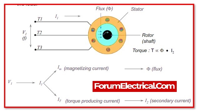
9). Torque Vector Control
Vector control implies asynchronous & DC motors possess the same torque mechanism. Vector control mode synthesizes stator current from magnetic current & torque current & outputs it to the motor. Thus, DC motor control performance is comparable. When torque vector control is used, especially in low-speed ac motors, the motor can generate output maximum torque.
Due to the VFD’s slip compensation according to the load current value & phase, the motor has a hard mechanical characteristic and can meet most system requirements without the speed feedback circuit in the VFD’s external. Enabling this functionality depends on the specific condition.
10). Energy-Saving Control
Fans and pumps are all decrease torque loads, meaning the load torque decreases that are proportional to the square of rotation speed in the speed decrease.
The VFD is designed with energy-saving control function dedicated V/F mode, which can improve the efficiency of the electric motor and VFD drive by automatically decreasing the output voltage according to load current. Enable (or) disable it as needed.

 parameters and their functionalities.)