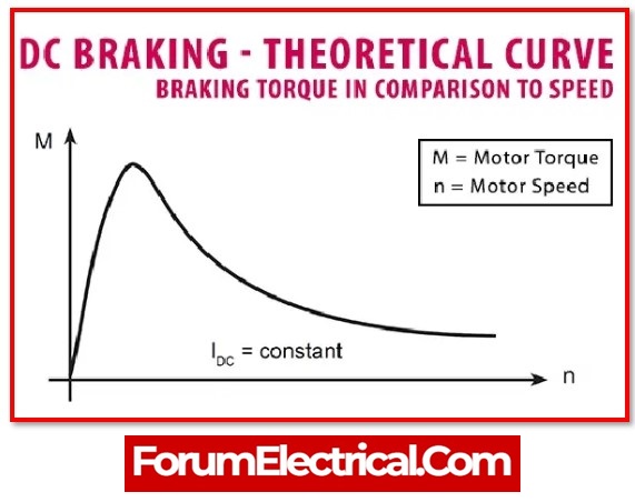
DC Injection braking is a system utilized with three-phase motors. The VFD generates a direct current that is applied to two of the motor’s windings, causing the motor to rapidly brake. DC injection braking is efficient only at speeds that are low (less than 8 Hz). DC Injection may also be utilized to heat up the motor and prevent water vapor from condensing in the motor windings. Keep in consideration that DC current delivered across a winding function as a short circuit, therefore current must be regulated and a time limit must be established.
VFD DC Injection Braking
DC injection braking in VFD constitutes one of the motor braking methods. This article will explain what DC braking is and how it works.
The motor should ideally cease after a stop order has been transmitted to the VFD. However, the motor continues to run and eventually comes to a stop. This is due to Newton’s law of inertia. Unless an external force applies against the motor torque, the motor continues to run. In most condition, it is due to air friction. However, in this condition, the motor comes to a stop slowly.
The motor continues to run after the VFD receives a stop command. When the frequency of the VFD is zero, the VFD infuses DC voltage into the stator winding. The VFD can inject voltage into one or more windings based on the required braking torque. After infusing DC into the winding, the motor comes to a halt. As a result, this technique of motor braking is known as DC Injection braking.
Let analyse how the DC Injection brakes the motor.
Function of VFD’s DC Injection Braking
When inject DC into the stator winding if the motor is running (with the supply turned off). A magnetic field is created by the stator winding. The voltage induced in the rotor winding when the rotor rotates under a magnetic field.
The braking torque generated by the motor is determined by the resistance of the windings & the current flowing between them. For each motor, the stator winding resistance is fixed. As a result, the braking torque is directly proportional to the stator current squared. The magnitude of the injected DC voltage determines the stator current.
As a result, can adjust the motor’s braking torque in the two methods that follow.
- By adding extra stator winding to the circuit, can increase stator resistance.
- By increase DC voltage – by changing this setting in the VFD.
DC Injection braking can generate a significant amount of braking torque. However, when the motor slowly rotates, all of the heat dissipated in the rotor winding. As a result, it has an impact on the winding’s insulating life.
The induction motor’s rotor winding has a short circuit at end rings. As a result of the induced voltage, current flows in the winding.
DC injection braking outperforms other motor braking types
Braking is an essential component of a motor with a VFD when utilizing the motor effectively. It determines how much energy the motor will utilize and dissipate overall, among other things.
The four DC injection braking methods used in motors the most frequently are
1). Coast to stop,
2). Ramp to stop,
3). Regenerative braking and
4). Dynamic braking
1). Coast to stop
The motor is disconnected from the VFD output source of power when coasted to stop.
This enables the motor to stop itself at a specific amount of time; or, to put it another way, it simply frees the motor from the action.
2). Ramp to stop
The term “ramp to stop” refers to the process which applies the motor deceleration time (the ramp-down time established in the VFD) in order to stop the motor within that period.
The motor is in no way turned off when the ramp comes to a stop.
3). Regenerative Braking
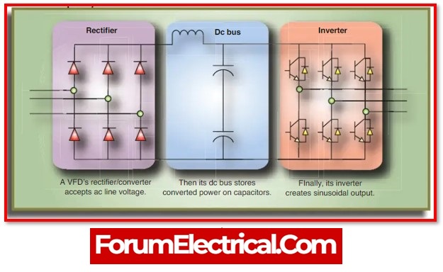
During the process of regenerative braking, energy is created and then stored in the capacitors of the DC bus.
When used in conditions where there is either a low amount of inertia or a substantial amount of friction load, this method is capable of fast stopping the motor.
However, if the load inertia is extremely high, a significant quantity of energy will be produced in the capacitors, which will result in an increase in voltage that is too high.
In spite of considering that the VFDs have a limitation in overvoltage, going above that limit will cause a malfunction and cause the VFD to trip.
4). Dynamic Braking
Dynamic braking is a substitute of regenerative braking. When the voltage above the limit, a dynamic braking resistor put across the bus will dissipate the additional energy in it. However, it increases the system’s size and complexity.
So, for high inertia loads, functioning at high speeds with them and employing these methods for braking can generate some level of instability, since they will take longer to stop because of natural forces and potentially damage the surrounding environment.
This demands the use of DC injection braking for the high inertia loads with speedy and safe stop action.
Advantage of DC Injection Braking
- DC braking modules contain no consumable parts and hence not need maintenance.
- Friction brakes require a mechanism of actuation, which can be either a human operator (or) a system-controlled actuator, contributing to the system’s complexity.
- A DC brake is simple to incorporate within the MCC – motor control circuitry.
Difference between DC and Dynamic Braking
| DC Braking | Dynamic Braking |
| DC Injection Braking is used for holding the load positioned after the motor been stopped working. This is accomplished by pumping DC voltage into the motor, which generates holding torque. When a big holding capacity is required, DC braking is not appropriate. | When regeneration from the motor causes an increasing in the drive’s DC bus voltage, dynamic braking is applied. The DC bus voltage might rise when the drive is running, accelerating, decelerating, or even stopping. The increase in bus voltage may result in a high DC voltage trip. |


