
- What is meant by Bridge Rectifier?
- Construction of Bridge Rectifier
- Circuit Diagram of a Bridge Rectifier
- Working Principle of a Bridge Rectifier
- Different Types of Bridge Rectifiers
- IC Bridge Rectifier
- Specifications of IC Bridge Rectifier
- Characteristics of Bridge Rectifier
- Waveform of a Bridge Rectifier
- Why is it a bridge rectifier?
- Why is a bridge rectifier equipped with four diodes?
- Advantages of a Bridge Rectifier
- Disadvantages of a Bridge Rectifier
- Applications of a Bridge Rectifier
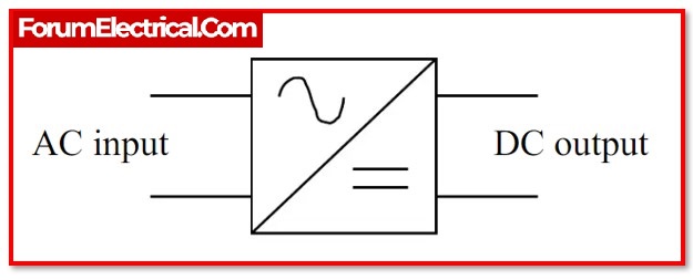
AC (Alternating Current) is transformed into DC (Direct Current) using the rectifier circuit.
- Half-wave rectifiers,
- Full-wave rectifiers, and
- Bridge rectifiers
are the three basic kinds of rectifiers. All of these rectifiers have the same primary purpose, which is to convert current, however they do not do so effectively while doing so.
Both
- The bridge rectifier and
- The centre tapped full wave rectifier
are effective converters.
Electronic power sources have bridge rectifier circuits. In order to power the numerous electronic fundamental components from the available AC mains supply, many electronic circuits need a rectified DC power source. This rectifier is used in a broad range of electronic AC power devices, including
- Welding applications,
- Modulation processes,
- Motor controllers, and
- Residential appliances.
A summary of a bridge rectifier’s operation is covered in this post.
What is meant by Bridge Rectifier?
An alternator that converts mains AC input to direct current (DC) output is known as a bridge rectifier. Bridge rectifiers deliver DC voltage to electrical devices and components. Any other regulated solid-state switch (or) four (or) more diodes may be used to assemble them.
Load current determines the bridge rectifier.When selecting a rectifier power source for an appropriate purpose in an electrical system, factors like
- Component ratings & specifications,
- Breakdown voltage,
- Temperature ranges,
- Transient current rating,
- Forward current rating,
- Mounting requirements, and
others are taken into consideration.
Construction of Bridge Rectifier
The four diodes D1, D2, D3, and D4 may be used in this circuit, alongside a load resistor (RL). To effectively convert AC to DC , these diodes may be connected in a closed-loop arrangement. This design’s key advantage is that it does not need a special center-tapped transformer. Thus, size and price will decrease.
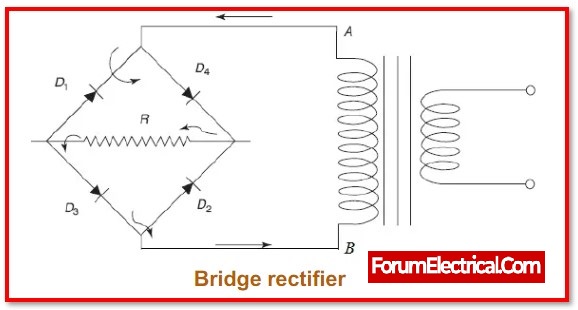
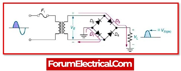
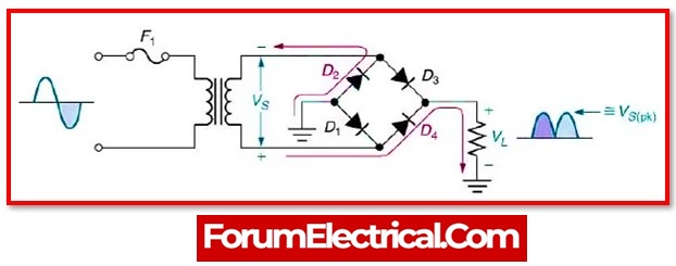
The output DC signal may be obtained across the RL after the input signal has been applied across two terminals, such as A & B. In this condition, a load resistor is attached between two terminals, C & D. The placement of two diodes may be done in such a manner that two diodes will conduct electricity during each half cycleD1 and D3 diode pairs will carry current during the positive (+) half cycle. D2 and D4 diodes conduct current during negative (-) half cycles.
Circuit Diagram of a Bridge Rectifier
A center-tapped transformer full-wave rectifier produces about half the output voltage of a bridge rectifier.Since it doesn’t require a center-tapped transformer, this circuit resembles a less cost rectifier.
The circuit diagram for a bridge rectifier includes many levels of components, including
- Transformer,
- Diode bridge,
- Filtering, and
- Regulators.
A regulated DC power supply is what all of these building blocks together are often referred to as, and it powers numerous electronic equipment.
1). Transformer
A step-down transformer that modifies the input voltage’s amplitude makes up the circuit’s initial stage. The majority of electronic projects step-down the 230V AC mains supply to 12V AC supply using a 230/12V transformer.
2). Diode Bridge
3). Filtering
Filtering is required to produce the output following the diode bridge rectifiers as a pure DC due to its pulsing nature. When the wave is smoothed, filtering is often carried out using one (or) more capacitors connected across the load. Output voltage impacts this capacitor rating.
4). Voltage Regulators
The voltage regulator that keeps the output voltage constant is the final step of this controlled DC supply. The microcontroller runs at 5V DC, while the bridge rectifier outputs 16V. In order to lower this value and ensure that it remains constant irrespective of whether the input voltage varies, a voltage regulator is required.
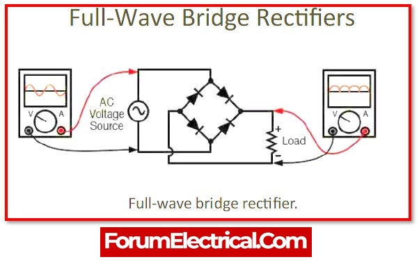
Working Principle of a Bridge Rectifier
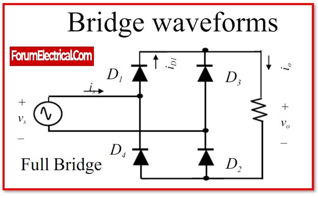
Four diodes comprise a single-phase bridge rectifier, which is linked across the load as previously explained.
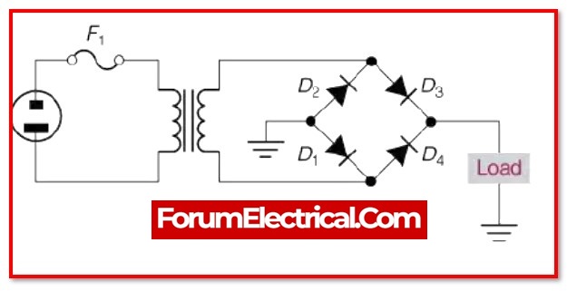
D1 and D2 are forward biased in the Positive half cycle for the AC input waveform diodes, while D3 and D4 are reverse biased. The load current takes when the voltage rises over the diodes’ threshold levels and they start conduct.
The diodes D3 and D4 are biased forward in the negative half cycle for the AC input waveform, while D1 and D2 are biased backward. When the D3 & D4 diodes begin to conduct, load current begins to flow through them.
The load current flow of direction is the same in both condition making the current unidirectional and hence DC. Thus, the input AC current is changed into a DC current by using a bridge rectifier. This bridge wave rectifier produces a pulsing output at the load, however generating a pure DC necessitates the use of an extra filter, such as a capacitor. Different bridge rectifiers may all be operated in the same way; however controlled rectifiers need thyristor triggering to push the current to the load.
Different Types of Bridge Rectifiers
Based on the following characteristics of the supply, the ability to regulate, the arrangement of the bridal circuit, and others, bride rectifiers are divided into different categories.
The two primary categories of bridge rectifiers are
- Single-phase rectifiersand
- Three-phase rectifiers.
These two categories are further divided into rectifiers that are
- Uncontrolledrectifiers,
- Half controlledrectifiers, and
- Fully controlledrectifiers.
Below is an overview of a few of these rectifier types.
1). Single Phase and Three Phase Rectifiers
These rectifiers are determined by the kind of supply, such as a single-phase (or) three-phase supply. Three-phase rectifiers use six diodes to convert AC to DC, whereas single-phase bridge rectifiers use four diodes.These rectifiers may again be regulated or uncontrolled, depending on the circuit’s diodes, thyristors, and other components.
2). Uncontrolled Bridge Rectifiers
This bridge rectifier employs diodes to correct the input. Because the diode is a uni-directional device, current is able to flow in one way through it. The rectifier’s diode arrangement prevents the power from changing in response to the demands of the load. In continuous or fixed power supply, this kind of rectifier is employed.
3). Controlled Bridge Rectifier
In this sort of rectifier,
- AC/DC converter (or)
- Rectifier,
controlled solid-state devices like
- SCRs,
- MOSFETs,
- IGBTs, etc.
are used to adjust the output power at various voltages in place of uncontrolled diodes.
It is possible to vary the output power (P) at the load in an appropriate way by activating these devices at different times.
IC Bridge Rectifier
The pin arrangement of a bridge rectifier similar to the RB-156 IC is explained below.
- Pin-1 (Phase / Line): The phase wire may be connected via the AC supply to this phase pin using the pin 1 (Phase/Line) AC input pin.
- Pin-2 (Neutral): It is the pin for the AC input, and it is here that the neutral wire may be connected from the AC supply.
- Pin-3 (Positive): This serves as the DC output pin from which the rectifier’s positive DC voltage is derived.
- Pin-4 (Negative/Ground): This is also the DC output pin, and it is from that negative pin that the rectifier’s ground voltage is derived.
Specifications of IC Bridge Rectifier
RB-15 bridge rectifier has subcategories in the range of RB15 to RB158. The RB156 is the rectifier that is utilised the most out of all of them. The following are some details about the RB-156 bridge rectifier.
- 1.5A is the O/p DC current.
- The highest reverse peak voltage is 800V.
- Voltage of the output: (-2VRMS) 2 Volt
- 560V is the maximum input voltage.
- Each bridge’s voltage loss is 1V at 1A.
- 50A is the surge current.
The most often used small, affordable, & single phase bridge rectifier is the RB-156. This IC may be utilised for 1-phase mains supply worldwide since it has the greatest I/p AC voltage of 560V. This rectifier can handle 1.5A of DC current at its maximum. The best option for projects converting AC-DC that provides up to 1.5A is this IC.
Characteristics of Bridge Rectifier
The following are some characteristics of bridge rectifiers.
- Ripple Factor
- Peak Inverse Voltage (PIV)
- Efficiency
1). Ripple Factor
The ripple factor is a unit used to quantify the smoothness of a DC output signal. A smooth DC signal be regarded as the o/p DC signal with few ripples, and the o/p with high ripples can be thought of as a high pulsing DC signal. Mathematically, it is the ratio of the DC voltage to the ripple voltage.
The ripple factor for the bridge rectifier may be expressed as
γ = √ [(Vrms/Vdc)2-1]
Where,
γ = Ripple Factor
Vrms= RMS Voltage
Vdc= DC Voltage
The bridge rectifier’s ripple factor is 0.48.
2). Peak Inverse Voltage (PIV)
When a diode is linked in reverse bias during the negative half cycle, the peak inverse voltage, or PIV, is the maximum voltage value that receives from the diode at that time. Bridge circuit diodes are D1, D2, D3, & D4.
The two diodes, D1 and D3, remain in the conducting position during the positive half of the cycle, while D2 and D4 are both in the non-conducting state. Diodes like D2 and D4 remain in the conducting position during the negative half cycle, while diodes like D1 and D3 remain in the non-conducting state.
3). Efficiency
A rectifier converts AC into DC is largely determined by its efficiency. The ratio between the DC output power and the AC input power may be used to determine the rectifier’s efficiency. The maximum efficiency of the bridge rectifier is 81.2%.
ή = DC Output Power/AC Input Power
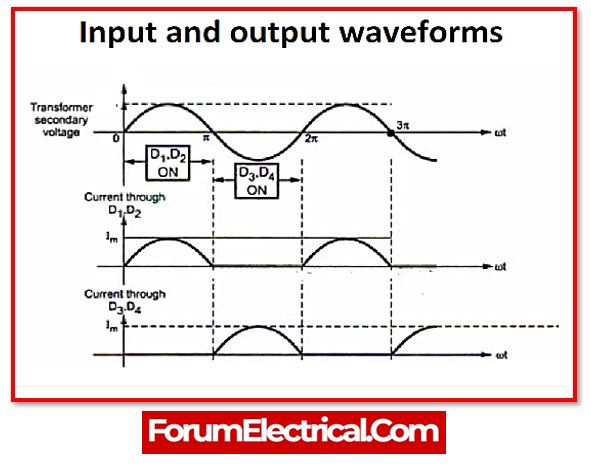
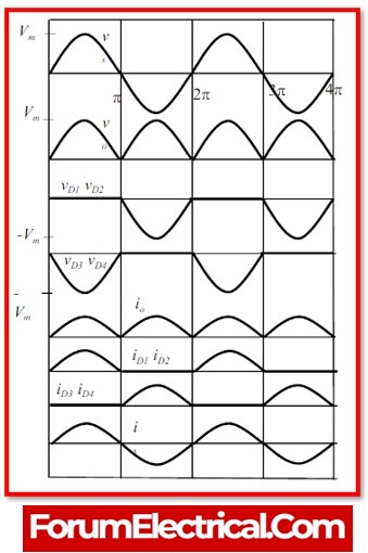
Waveform of a Bridge Rectifier
From bridge rectifier circuit’s layout that there is equal current flow across the load resistor for both the positive and negative half cycles. The o/p DC signal’s polarity may either be completely positive or completely negative. It is entirely positive in this instance. A completely negative DC voltage is possible once the direction of the diode is reversed.
As a result, this rectifier permits current to flow during both the positive and negative cycles of the input AC signal.
Why is it a bridge rectifier?
This particular type of rectifier circuit is the most effective one when compared to others. This particular type of full-wave rectifier employs four diodes that are coupled in a bridge configuration, as the name would imply. A bridge rectifier is the term given to this kind of rectifier.
Why is a bridge rectifier equipped with four diodes?
Four diodes are utilised to create a bridge rectifier circuit that enables full-wave rectification without the need for a center-tapped transformer. In the majority of applications, this rectifier is primarily employed to provide full-wave rectification.
To effectively convert AC to DC, four diodes may be arranged in a closed-loop configuration. The absence of the center-tapped transformer reduces both size and cost, which is the fundamental advantage of this configuration.
Advantages of a Bridge Rectifier
- A full-wave rectifier has a rectification efficiency that is twice as high as a half-wave rectifier.
- For of a full-wave rectifier, the greater output voltage, output power, and Transformer Utilisation Factor.
- In the event of a full-wave rectifier, the ripple voltage is low & of greater frequency, hence a simple filtering circuit is necessary.
- In the event of a bridge rectifier, the necessary transformer is simpler since no centre tap is needed in the transformer secondary. The transformer may even be removed if voltage stepping up or down is not necessary.
- In the event of the bridge rectifier, a smaller power transformer may be employed for a given power output since the supply transformer’s main and secondary windings are both conducting current during the full ac cycle.
- Compared to a half-wave rectifier, the efficiency of rectification is twice.
- Simple filter circuits are used for low ripple voltage and high frequency.
- Compared to a center-tapped rectifier, TUF is greater.
- No centre tap transformer is required.
Disadvantages of a Bridge Rectifier
- Four diodes are needed.
- The output voltage is decreased by the increased voltage drop brought on by the usage of two extra diodes.
- This rectifier requires four diodes; hence its price will be considerable.
- Because the two diodes may be connected in series and produce a twofold voltage drop due to their internal resistance, the circuit is inappropriate whenever a low voltage has to be rectified.
- They are very intricate (complicated) circuits.
- The bridge rectifier loses more power than the center-tapped type rectifier.
Applications of a Bridge Rectifier
- In the process of modulating radio signals, bridge rectifiers provide an important function.
- They are put to use in the process of converting high AC-voltage into low DC-voltage.
- In addition to that, they are used in electric welding.
- The primary function of bridge rectifiers is that of power supply units.