
- Overview
- ACS712 Current Sensor
- Pin Diagram of ACS712 Current Sensor
- Types of ACS712 Current Sensors
- Selecting an Appropriate ACS712 Current Sensor
- Sensor Specifications
- Arduino-Based ACS712 Wiring Schematic Diagram
- Code for DC Current Measurement
- ACS712 Arduino AC Current Wiring Diagram
- Code for measuring AC current
- Displaying Current on the LCD
- Code for displaying current on the LCD
- Conclusion
Overview
The ACS712 is a Hall Effect current sensor that can measure both AC and DC current. It is an effective option to be utilized with Arduino since it is simple to use and produces reliable results.
In the following post, we will demonstrate how to measure current with Arduino & ACS712 current sensor. We will also go over the different kinds of ACS712 current sensors available & how to choose the best one for your purposes.
ACS712 Current Sensor
The ACS712 is a Hall effect linear current sensor that can detect both AC and DC currents.
It is made up of a Hall sensor & a low-ohmic current pathway, which allows it to produce a voltage output proportional to the current flowing through it.
The ACS712, which is available in various current ranges such as 5A, 20A, and 30A, is widely used in Arduino projects for the real-time current monitoring.
To utilize it, connect the sensor to the Arduino, read the analog data, then convert them to actual current measurements using the sensor’s sensitivity.
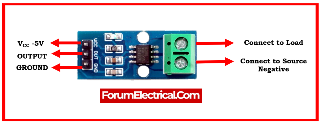
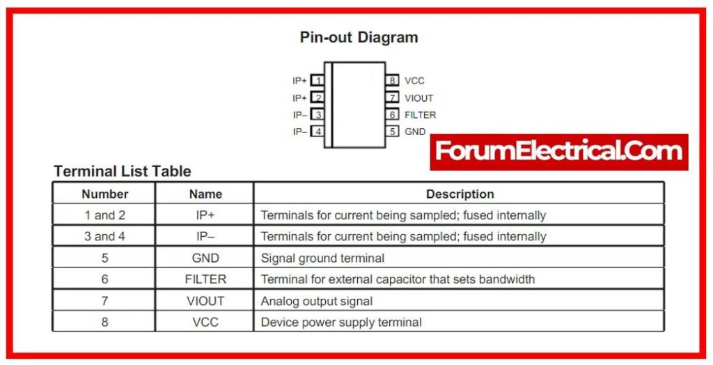
Pin Diagram of ACS712 Current Sensor
Types of ACS712 Current Sensors
The ACS712 current sensors can be found in three primary types:
ACS712EL
A low-current sensor with a maximum current measurement of 5 amps is the ACS712EL.
ACS712ELC
The center-hole design of the low-current ACS712ELC sensor facilitates easy installation.
ACS712-20A
A high-current sensor with a 20 amps maximum current measurement capacity is the ACS712-20A.
Selecting an Appropriate ACS712 Current Sensor
When selecting an ACS712 current sensor, the following elements should be taken into consideration:
Current range: Maximum Current
Accuracy: Exact Measurement
Bandwidth: Highest Frequency
Cost: Sensor Cost
Sensor Specifications
| 5A Module | 20A Module | 30A Module | |
| Supply Voltage VCC | 5VDC | 5VDC | 5VDC |
| Measurement Range | -5 to +5 Amps | -20 to +20 Amps | -30 to +30 Amps |
| Voltage at 0A | VCC/2 | VCC/2 | VCC/2 |
| Scale Factor | 185mV/A | 100mV/A | 66mV/A |
| Chip | ACS712ELC (5A) | ACS712ELC (20A) | ACS712ELC (30A) |
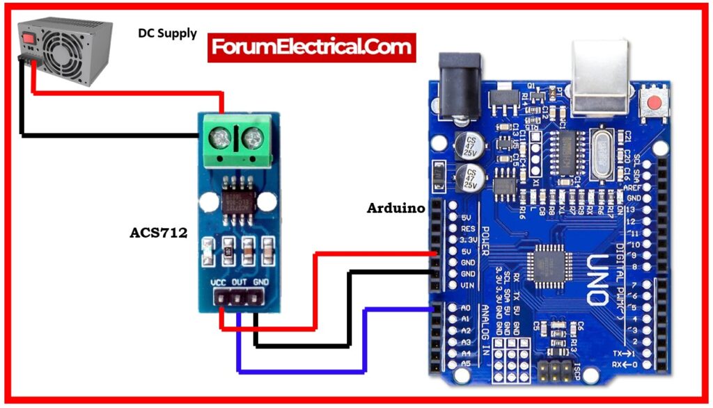
Arduino-Based ACS712 Wiring Schematic Diagram
The diagram appears to be a basic setup for measuring DC current with an analog pin (A0) & converting the analog value to current. However, there are several factors to consider. They appear to be assuming a voltage offset of 2.5V & a conversion factor of 0.185, however these values may differ based on your particular circuit.
Code for DC Current Measurement
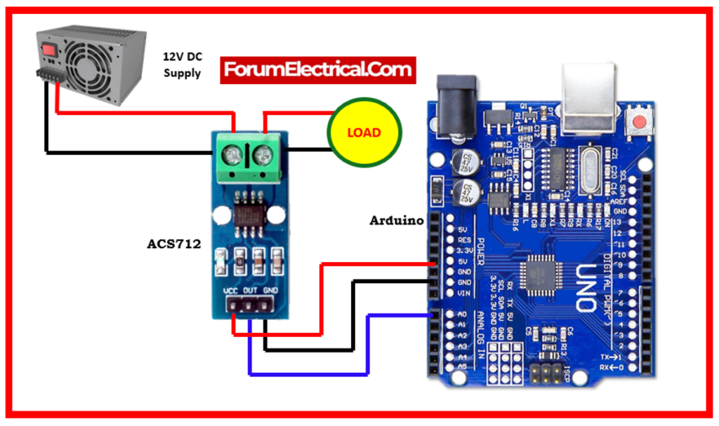
If capable of measuring the current flowing through a 12V DC light from a 12V power source. As a result, here is the schematic of the wiring.
To measure DC current employing the ACS712 and an Arduino, follow the wiring demonstrated below. The ACS712 sensor is ideal for DC current measurements, & the diagram below assumes a 5A range ACS712 module.
Here’s an improved version of the schematic with some enhancements and a reminder to alter the voltage offset & conversion factor based on the particular configuration:
Wiring Diagram:
- Connect ACS712 to Arduino.
- ConnectACS712 VCC to Arduino 5V.
- Connect ACS712 GND to Arduino GND
- Connect ACS712 Output to Arduino Analog Pin (e.g., A0)
CODE:
void setup() {
// Enter the setup code here, to run once:
Serial.begin(9600);
}
void loop() {
// Enter the primary code here, to run repeatedly:
int adcValue = analogRead(A0);
float voltage = adcValue * (5.0 / 1023.0); // Convert ADC to voltage value
float current = (voltage – 2.5) / 0.185; // Adjust 2.5 and 0.185 based on your setup
Serial.print(“ADC Value: “);
Serial.print(adcValue);
Serial.print(“\tVoltage: “);
Serial.print(voltage, 3); // Print voltage with 3 decimal places
Serial.print(” V\tCurrent: “);
Serial.print(current, 3); // Print current with 3 decimal places
Serial.println(” A”);
delay(300);
}
Note:
- We included comments to help others understand.
- We changed the variable names for clarification.
- The voltage & current are printed with a total of 3 decimal places for greater precision.
- Please make sure to adapt the voltage offset (2.5) & conversion factor (0.185) to the particular circuit and calibration. If you are unsure about these numbers, you may need to calibrate the sensor (or) consult the specifications for the sensor (or) module that are utilizing.
When not loaded, the drawing above may make some noise. So can ignore noise by discarding readings below a specific value. ignore the reading below 0.16 A.
ACS712 Arduino AC Current Wiring Diagram
This is a wiring diagram for connecting the ACS712 to an Arduino to measure AC current. For this example, assume that utilizing the ACS712 sensor with a 5A range.
The ACS712 sensor is the polarity-sensitive. Make sure to connect it in the proper orientation to measure current flow in the appropriate direction.
Wiring Diagram:
- Connect the ACS712 to Arduino.
- ACS712 VCC to Arduino 5 volts
- ACS712 GND to Arduino GND.
- ACS712 OUT to Arduino Analog Pin (such as A0)
Connect the ACS712 to an AC circuit:
- Connect the ACS712 V+ and V- to the section of the circuit where you wish to measure current.
- Examine polarity.
Code for measuring AC current 
void setup() {
Serial.begin(9600);
}
void loop() {
// Read ACS712 output voltage
int sensorValue = analogRead(A0);
// Convert ADC reading to voltage (assuming 5V Arduino)
float voltage = sensorValue * (5.0 / 1023.0);
// Calculate current (for 5A ACS712 module)
float current = (voltage – 2.5) / 0.185;
// Print the results
Serial.print(“Sensor Value: “);
Serial.print(sensorValue);
Serial.print(“\tVoltage: “);
Serial.print(voltage, 3);
Serial.print(” V\tCurrent: “);
Serial.print(current, 3);
Serial.println(” A”);
delay(1000); // Delay for readability, adjust as needed
}
Note:
Modify the current conversion factor (0.185) according to the ACS712 module’s specifications. Refer to the ACS712 module datasheet to get the correct value for the configuration.
Displaying Current on the LCD
This wiring diagram can be used to show the current on an LCD.
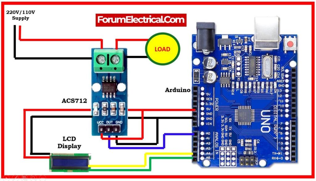
It is necessary to connect an LCD to an Arduino and adjust the code in order to present the current measurement on an Liquid Crystal Display in conjunction with the Arduino and ACS712 configuration. This is an illustration utilizing a standard 16×2 character LCD.
LCD Wiring Diagram:
- Connect the LCD’s VCC pin to the Arduino 5V.
- Connect LCD’s GND pin to Arduino’s GND.
- Connect LCD’s SDA pin to Arduino A4 to enable I2C communication.
- Connect LCD’s SCL pin to the Arduino A5 to enable I2C communication.
Code for displaying current on the LCD
#include <Wire.h>
#include <LiquidCrystal_I2C.h>
LiquidCrystal_I2C lcd(0x27, 16, 2); // I2C address 0x27, 16 column and 2 rows
void setup() {
Serial.begin(9600);
lcd.begin(16, 2); // initialize the lcd
}
void loop() {
// Read ACS712 output voltage
int sensorValue = analogRead(A0);
// Convert ADC reading to voltage (assuming 5V Arduino)
float voltage = sensorValue * (5.0 / 1023.0);
// Calculate current (for 5A ACS712 module)
float current = (voltage – 2.5) / 0.185;
// Print the results to Serial
Serial.print(“Sensor Value: “);
Serial.print(sensorValue);
Serial.print(“\tVoltage: “);
Serial.print(voltage, 3);
Serial.print(” V\tCurrent: “);
Serial.print(current, 3);
Serial.println(” A”);
// Display the results on the LCD
lcd.clear(); // Clear the LCD screen
lcd.setCursor(0, 0); // Set the cursor to the first column of the first row
lcd.print(“Current: “);
lcd.print(current, 3);
lcd.print(” A”);
delay(1000); // Delay for readability, adjust as needed
}
Note:
This code makes advantage of the “LiquidCrystal_I2C” library to communicate more easily with the LCD. Before uploading the code to the Arduino, ensure that the have installed the library using the Arduino IDE’s Library Manager. Alter the I2C address (0x27) in LiquidCrystal_I2C lcd(0x27, 16, 2); line to match the LCD module.
Conclusion
Arduino & the ACS712 current sensor make current measurement simpler. Arduino can detect current accurately and dependably with some effort.
Additional Arduino and ACS712 current sensor measurement tips:
- Utilize a power supply that can power the Arduino and ACS712 current sensor.
- Utilize a heatsink on the ACS712 current sensor for high-current measurements.
- It can increase present measurement accuracy with a calibration factor. The ACS712 current sensor datasheet has the calibration factor.
- It can library simplifies reading the ACS712 current sensor voltage and converts it to current.