
When selecting a generator for a certain application, it is necessary to take into consideration generator requirements, which are the parameters and requirements that must be taken into consideration.
The accurate power requirements of the system, the surrounding conditions, and the intended use of the system all serve an importance in determining different requirements.
Determining generator requirements is a systematic process that ensures the chosen generator fulfills the unique needs of your application.
This post is a step-by-step guide to assist you establish the generator requirements.
Consideration should be given to the following common generating requirements:
Overview
According to the International Electrotechnical Commission (IEC) 60034, the generator must be developed, established, and tested.
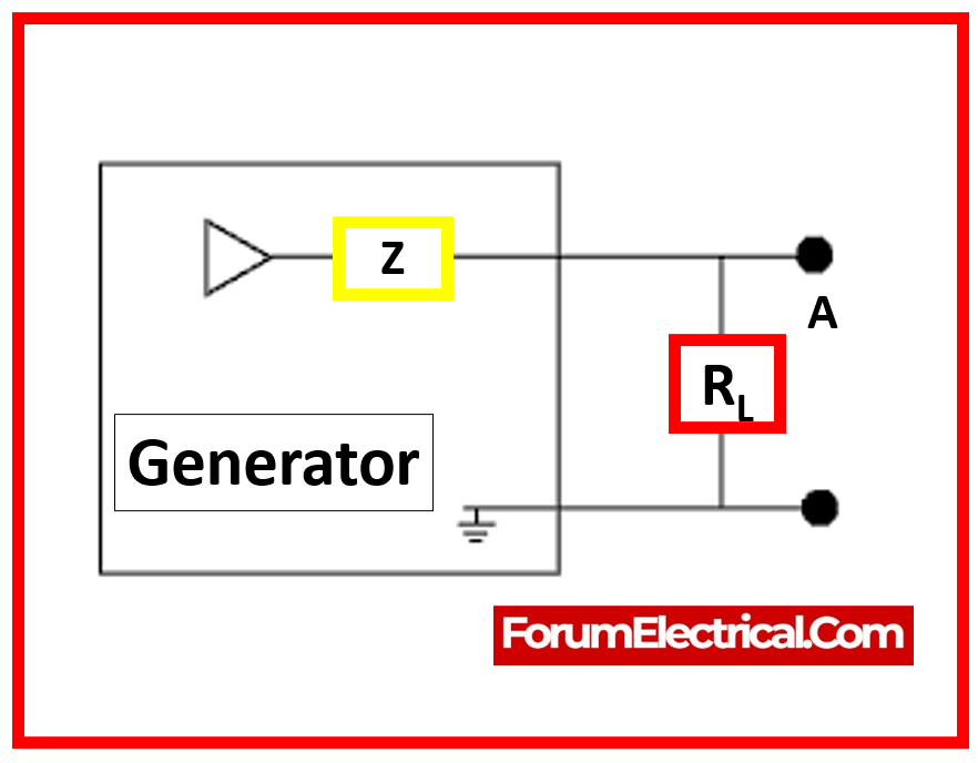
1). Generator Impedances
The datasheet needs to indicate the lowest & maximum sub-transient & transient impedances, as well as the maximum tolerances.
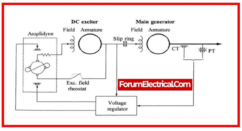
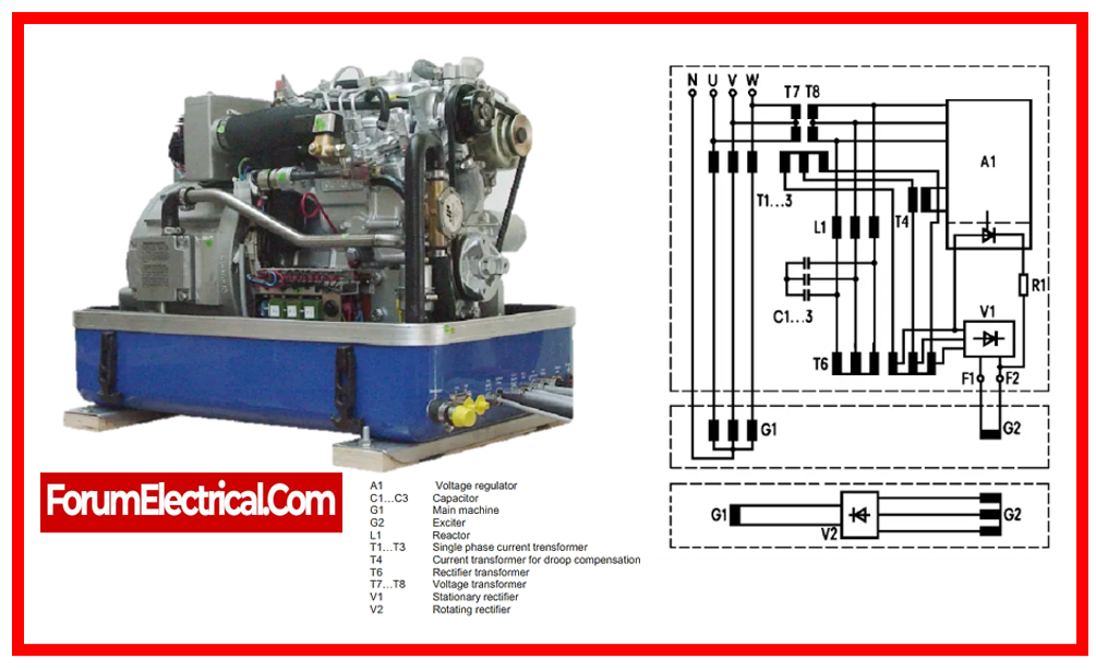
2). Excitation System
The generator must be self-exciting, which means it must create its nominal voltage without the usage of external power sources, even after long inactive (ideal) periods or a short circuit.
The excitation system must contain the following:
- Excitation equipment
- AVR
- Voltage adjuster (rheostat)
- Alarm for voltage failure (AVR).
Alongside brushless excitation, static excitation using voltage & current transformer circuits, with the generator rotor current provided by slip rings and brushes, is suitable.
The AVR must be electronic in design and include a precise voltage adjustment. It must have frequency detection circuitry to control the ceiling voltage and protect components while the generator is operated at low speeds, including when starting or idling.
Where excitation power is obtained from terminal voltage, current boost circuitry must be incorporated to provide excitation during short circuit circumstances and to sustain a short circuit current larger than 300% of the nominal current for 3 seconds.
The AVR must be suited to the generator’s characteristics and have suitable build and design to satisfy all operational & performance specifications.
The AVR must be capable of frequency dependent constant voltage
- U = constant down to 90% rated frequency &
- Adjustable slope (U/f) capabilities.
The AVR must be put in the generator’s control panel.
AVR installation at the generator is dependent on COMPANY approval, or as described in the RFQ. In this case, the AVR must be housed separately or in a clearly defined part of the primary terminal box.
The rated excitation current must be a minimum of 110% of the excitation current at the generator’s rated output under the most rigorous operational conditions.
The excitation system must be able to manage any field pushing conditions that the generator needs to provide such as starting massive motors.
The field forcing capability must be adequate to allow appropriately rated relay settings to be created for systems fault current protection.
The rated voltage of the excitation system must be at least 110% of the rotor voltage at the generator’s rated output under the most demanding conditions. The ceiling voltage must not be less than 120% of exciter’s rated voltage.
3). Output Voltage Variations
The voltage regulation of generator must be grade VR2.31 in order to comply with BS 4999 Part 140. If higher levels of voltage regulation is needed due to the associated loads, it must be indicated in the demand.
4). Efficiency
The generator efficiency at the nominal load & power factor of 0.8 must be no less than 91%.
The manufacturer will provide assured numbers for efficiency at 50%, 75%, and 100% of the rated output.
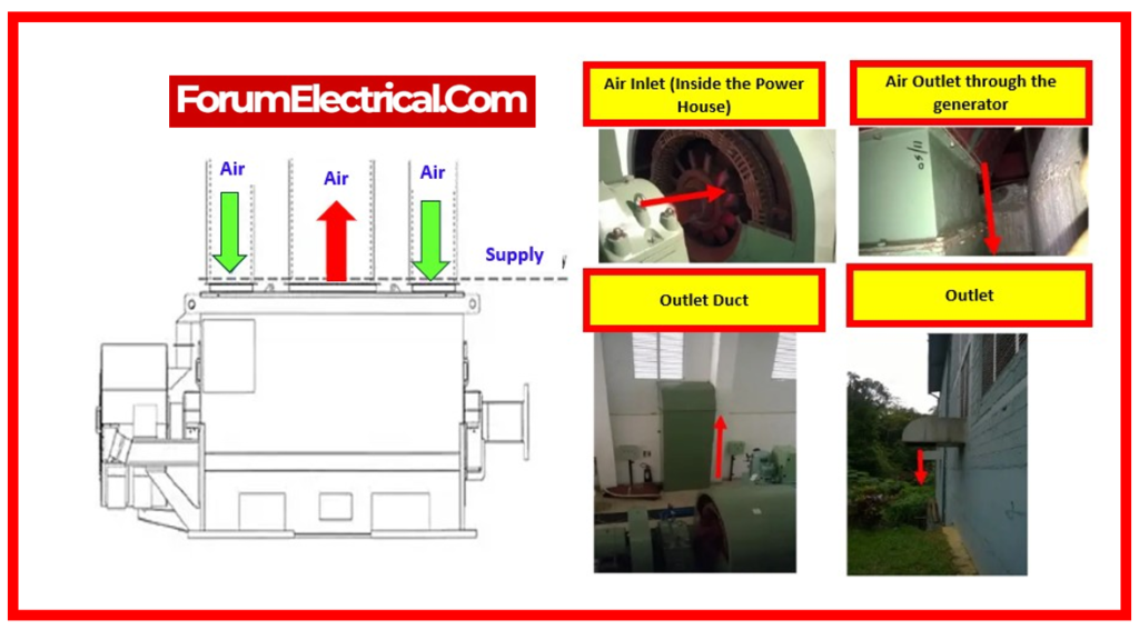
5). Generator Cooling
Generator cooling options include
- Self-Cooled Open (IC 01) and
- Air-to-Air (IC 0141/0151/0161/0166).
- Air-to-Water (IC W 37 A 81)
The designations are consistent with IEC 60034-6.
The desired cooling method must be indicated in the demand.
6). Generator Housing
The ingress protection of enclosures for generators and their auxiliaries designed for outdoor installation must be at least IP 55.
The generator & exciter enclosures must be equipped with proper inspection plates & access covers that are designed for rapid and easy removal.
Access covers for spinning excitation rectifier equipment must be large enough to allow people to do maintenance with both hands.
The generator must be equipped with an exterior earthing termination bolt that has been clearly identified with the relevant symbol.
7). Control & Protection Equipment
General
The generator set requires the following monitoring, control, and protection equipment:
- Local gauge panel for engine
- Engine control panel
- Generator control panel.
The engine and generator control panels may be merged into a single freestanding cubicle. A clear physical separation between engine & generator controls is required.
Control Panel Features
- The generator control panel should feature the following:
- Generator control and protection devices
- AVR
- Complete AC sub-distribution for space heaters, panel heaters, and other auxiliary items.
- Provides battery-backed DC power supply for generator protection systems, which can be integrated with engine protection systems.
- Raise/lower voltage adjuster behind panel door
- Generator status, alarm, and trip functions
- Generator voltage meter with 7-step selector switch
- One generator line current meter for each phase.
- Meters for power, frequency, and power factor.
- The manufacturer must provide information on the planned actual layout of the generator set & its auxiliaries, the preferred position of the required current and voltage transformers, & the location of the control & protection cubicles.
- All meters must be at least 72 mm square and have an accuracy class of 1.5, according to IEC 51.
Electrical Protection Requirements
- All protective relays must be digital electronic in nature and positioned in an easily accessible location.
- Components that require inspection or adjustment must be accessible from the floor level.
- Protection relays must be clearly labeled and fitted with visible flag indicators (or) other forms of indication commonly used on electronic type relays, such as LEDs.
- Protection relays must have manual reset capabilities and be insensitive to vibration, shocks, or transients.
- Dust-proof flush-mounted protective relays that are detachable and have calibration and testing capabilities should be provided.
- When withdrawable protection relays are removed, the terminals attached to current transformers must be automatically short-circuited.
- Multiple function aspects, such as tripping & alarm tasks, must have own operating connections and be sent to distinct terminals.
- Current transformers (CT) for overcurrent protection must have an appropriate Voltage-Ampere rating and precision to energize relays without damaging them over the spectrum of possible short circuit currents.
- Contact rating & performance must be consistent with IEC 60255.
8). Packaging Requirements
Baseplate
The baseplate must be constructed to withstand transit and lifting conditions. When designing the package, a horizontal force equivalent to the total transport weight can be assumed. Lifting shock forces should be considered, especially for offshore installations.
All welding must conform with ANSI/AWS D1.1 (or) the applicable local code.
The baseplate must be designed in such a way that it is not disruptive with engine and generator maintenance or routine servicing. No fuel pipe may be concealed in the baseplate.
The baseplate must be capable of withstanding any dynamic forces generated by the anti-vibration mounts.
Lifting lugs must be designed to support a load equivalent to twice the total assembly weight and must conform with ANSI/AWS D1.1 (or) the applicable local code. Prior to welding, the material where the lifting lugs will be welded must be ultrasonically examined for laminations.
Pipe & Interface Connections
The Packager must provide all on-baseplate plumbing for gasoline, lubricating oil, starting systems, and coolants. Connectors to the primary plumbing must be made at the baseplate edge using suitably rated ANSI/ASME B16.5 flanged connectors.
Painting
The engine & generator will be painted in accordance with the manufacturer’s specifications.
The specification must contain paint materials, surface preparation, application, film thickness, and data sheets from the paint supplier. Stainless steel components should not be painted.
Acoustic Enclosure
The acoustic enclosure must provide access for routine online maintenance and overhaul of the encased equipment.
All doors must be outfitted with emergency opening bars inside.
Opening any access door while generator set operation will result in an alarm, but will not cause the generator set to shut down.
Nameplates
The generator set’s components must have nameplates that match their specifications. The nameplate stated herein will apply to the entire package.
The following information must be marked clearly on a corrosion-resistant, non-destructible, permanent name/rating plate affixed to a permanent component of the generator control panel with detail of:
- Purchaser order number
- Year of manufacture
- Serial number
- Nominal output power.