
- Overview
- Introduction
- Methodology
- Block Diagram
- Modeling and Analysis
- Design Procedure
- GSM Interfacing with Microcontroller
- Hardware Implementation – Primary Components
- Software Requirements
- Working
- General Pin Functions
- Special Pin Functions
- Result
- Advantages of GSM based Substation Monitoring and Control System
- Disadvantage of GSM based Substation Monitoring and Control System
- Applications of GSM based Substation Monitoring and Control System
- Conclusion
Overview
This project analyzes remote electrical characteristics like voltage, current, and frequency and sends them over GSM using a modem/phone and power station temperature.
This project uses a SPDT relay to protect electrical wiring. This relay activates when electrical parameters exceed predefined values. Main power can be turned off with the relay. Send SMS commands to read remote electrical parameters.
This device can also deliver real-time electrical parameters via SMS based on time settings. This system can send SMS notifications when the relay trips (or) voltage (or) current exceeds limitations.
This project uses microcontrollers. The controller communicates well with sensors. A controller has internal memory for code.
The controller receives assembly instructions from this memory. The controller relies on these assembly instructions. The controller is programmed in embedded C.
Introduction
The power of electricity is essential. Modern industrialized environment depends increasingly on it. Massive, non-linear, complex electricity networks.
Unified power systems boost reliability, efficiency, & cost. Breakdown of this important national & global infrastructure has major direct and indirect consequences on the economy & national security.
Power systems have
- Generators,
- Lines,
- Transformers,
- Loads,
- Switches, &
- Compensators.
Many modern power systems contain many sources & loads. Power transmission & distribution subsystems have evolved.
Transmission systems deliver power from generators to consumers, while distribution systems link high voltage (HV) transmission networks to consumer services.
From the distribution system, feeders, distributors, & service mains supply power to clients.
Electricity requires
- Generation,
- Transmission, and
- Distribution.
Utility substations generates power independently in transmission and distribution.
Substations are compact buildings featuring
- Transformers,
- Switches,
- Voltage regulators, &
- Metering equipment
- To change voltages and monitor circuits.
As power systems reach their performance limitations and operate normally, reliable & efficient networks are not important.
A substation comprises of:
1) Transmission
2). Distribution.
The project focuses on the substation distribution because transmission cables carry power hundreds of miles from main stations.
Transferring generated electricity have power losses, reducing substation power.
Maintaining power supply quality requires sending end station and user end measurements.
Understanding the limit improves overall solution power and insufficient power system protection, monitoring, & control. System instability may arise.
A system that automatically identifies, monitors, & classifies electrical line limitations is needed.
Methodology
GSM technology is employed in this project to monitor and regulate the substation’s parameters.
This allows multiple substations to communicate with the station, and important conditions are communicated to the main power grid on a regular basis via GSM modem.
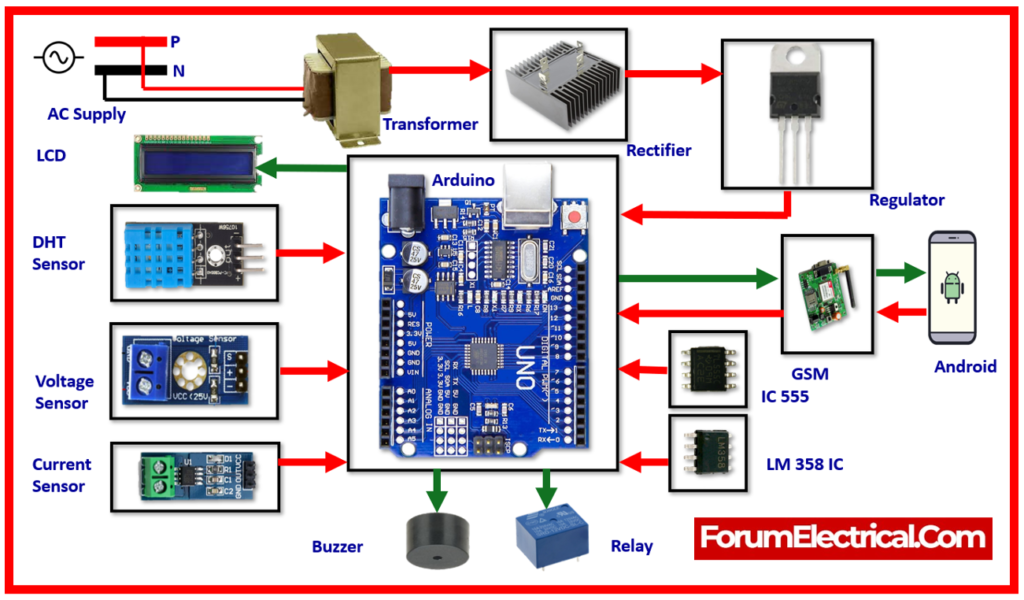
Block Diagram
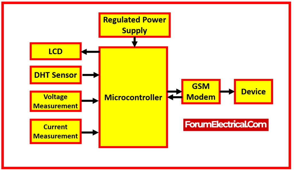
Modeling and Analysis
This block diagram above provides an overview of the key functions of monitoring remotely. The elements are represented to demonstrate the general appearance of the hardware.
In this design, the microcontroller is the fundamental device, controlled by 5v supplied by the rectifier and step-down by the transformer that delivers 230V.
The microcontroller has interference with the LCD, which displays current & voltage data on a frequent basis.
1). Power Supply
A required DC voltage is able to be obtained from the power supply to power the circuits.
The needed DC voltage is 5V DC, while the voltage we receive from the main line is 230V AC.
To get the desired voltage, a step-down transformer is employed. The transformer steps down the voltage to 12V AC, which is subsequently transformed to 12V DC using a rectifier.
Even though the output from the rectifier is a DC signal, it contains ripples, which is known as pulsating DC.
To remove these ripples, filter circuits are employed to provide smoothed DC electricity. A positive voltage regulator chip converts the 12V DC to 5V. Finally, a fixed DC voltage of 5V is established.
2). Microcontroller
A microcontroller is a component on a PC chip that includes a number of peripherals such as RAM and EPROM that execute a predefined function.
Different microcontrollers are utilized to execute specific tasks depending on their capabilities and feasibility.
The microcontroller sends & receives data of 8 bits.
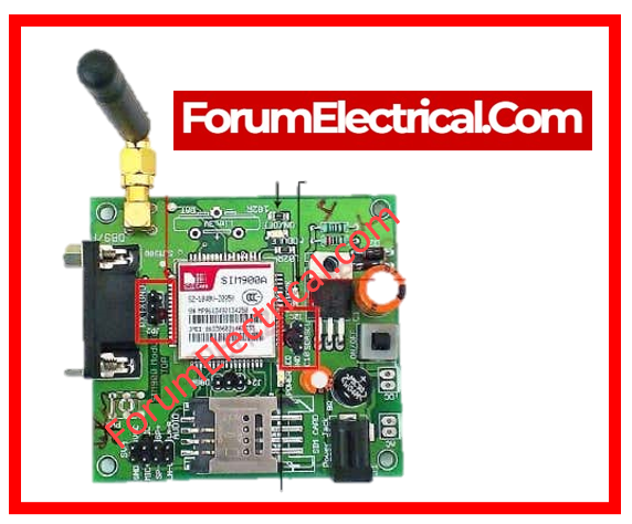
3). GSM Modem
It is a wireless modem which communicates via a GSM wireless network. Wireless modems are similar to dial-up modems.
The only difference here is that a dial-up modem receives & sends data via a telephone line, whereas a wireless modem receives & sends data via waves.
GSM modems, like GSM portables, require a SIM card. SIM 300 is a fixed cellular terminal (FCT) that is utilized in data applications. Its tiny shape and portable terminal allow for many types of data transfers over GSM.
The GSM modem can also be connected to a computer via a regular RS232C serial interface. SIM 300’s functions include SMS, data services, fax services, and data file access.
It additionally provides a wide range of applications in IT firms, banks, financial institutions, remote project sites, service providers, and many more.
Design Procedure
Step-1. LCD & data register interface parameters.
Step-2. Choose settings for circuit relays, LEDs, LCDs, and analog inputs.
Step-3. Initialize the microcontroller’s input and output ports.
Step-4. Displays parameter values.
GSM Interfacing with Microcontroller
It is necessary to use AT instructions in order to communicate with a GSM modem.
The microcontroller is responsible for transmitting these commands to the GSM modem, which is subsequently operationalized in order to carry out the necessary operation.
When it comes to controlling the operations of a GSM modem, the subsequent AT commands are usually considered in usage.
Hardware Implementation – Primary Components
1). Arduino UNO
2). GSM Modem
3). Relay
4). Voltage Sensor
5). Current Sensor
6). Buzzer
7). LCD display
8). IC555
9). DHT sensor
10). Rectifier
11). Regulator
12). LM 358 IC
1). Arduino UNO
Arduino.cc developed the Arduino UNO, an open-source microcontroller board based on the Microchip ATmega328P microcontroller.
The board includes sets of digital & analog input/output (I/O) pins that can be used to connect to various expansion boards (shields) and circuits.
The board contains 14 digital and 6 analog pins and can be programmed with the Arduino (Integrated Development Environment) using a type B USB connector.
It can be powered by a USB cable or an external 9V battery, and it manages voltages ranging from 7V to 20V.
It’s also comparable to the Arduino Nano & Leonardo.

Technical Specifications
- Microcontroller: Microchip ATmega328P
- Operating Voltage: 5 Volts
- Input Voltage: 7 to 20 Volts
- Digital I/O Pins: 14 (6 pin – PWM output)
- Analog Input Pins: 6
- DC Current per I/O Pin: 20 mA
- DC Current to 3.3V Pin: 50 mA
- Flash Memory: 32 KB in that 0.5 KB utilized by bootloader
- SRAM: 2 KB
- EEPROM: 1 KB
- Clock Speed: 16 MHz
- Length: 68.6 mm
- Width: 53.4 mm
2). GSM Modem
A GSM modem is a type of modem that supports a SIM card and operates similarly to a cell phone via a mobile operator subscription. From the point of views of mobile operators, a GSM modem looks exactly like a phone.
The GSM system is circuit-switched, dividing each 200 kHz channel into eight 25 kHz time slots.
The GSM uses the narrowband Time Division Multiple Access (TDMA) technology to transmit signals.
GSM was created utilizing digital technologies. It can carry data rates ranging from 64 kbps to 120 Mbps. Currently, GSM supports more than one billion mobile subscribers.
GSM provides phone and data services ranging from basic to advanced, as well as roaming. Roaming refers to the ability to utilize your GSM phone number in another GSM network.
A GSM digitizes and compresses data before sending it along a channel. It operates in either 900 MHz (or)1,800 MHz frequency range.
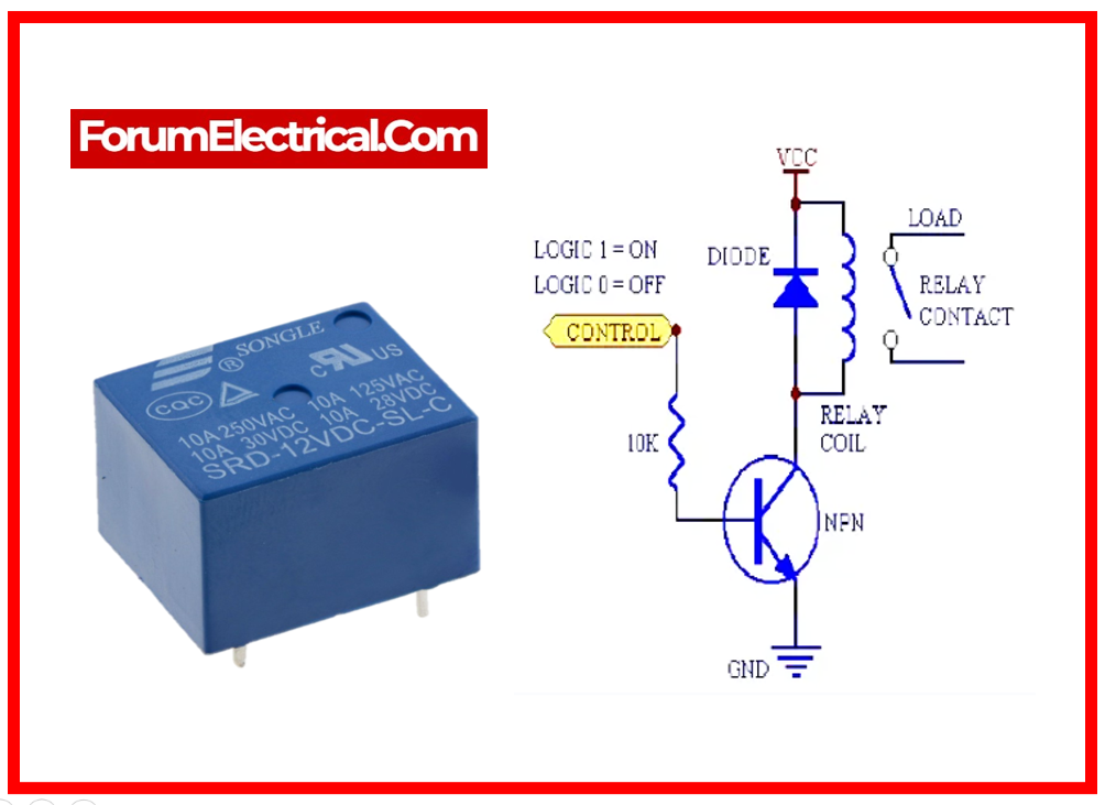
3). Relay
Relays are electronic and electromechanical switches that close and open circuits. It controls the opening and shutting of electronic circuit connections. When the relay connection is open (NO), the relay does not activate.
Relays are electrical switches that can be controlled remotely utilizing low current to regulate high current loads.
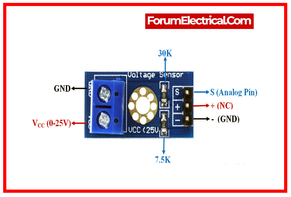
4). Voltage Sensor
A voltage sensor is a device that measures and monitors the voltage level in a component. The voltage sensors determine either the AC voltage (or) the degree of DC voltage. This sensor’s input might be voltage, and its output could be switches, an analog voltage signal, a present signal, an auditory signal, and so on.
The voltage sensor is based on the resistance point pressure principle. It can reduce the input voltage of the red terminal by five times the original value. The maximum Arduino analog input voltage is 5V, hence the sensor’s input voltage should not exceed 5 V x 5 = 25 V (if using a 3.3 V system, the input voltage must not exceed 3.3 V x 5 = 16.5 V).
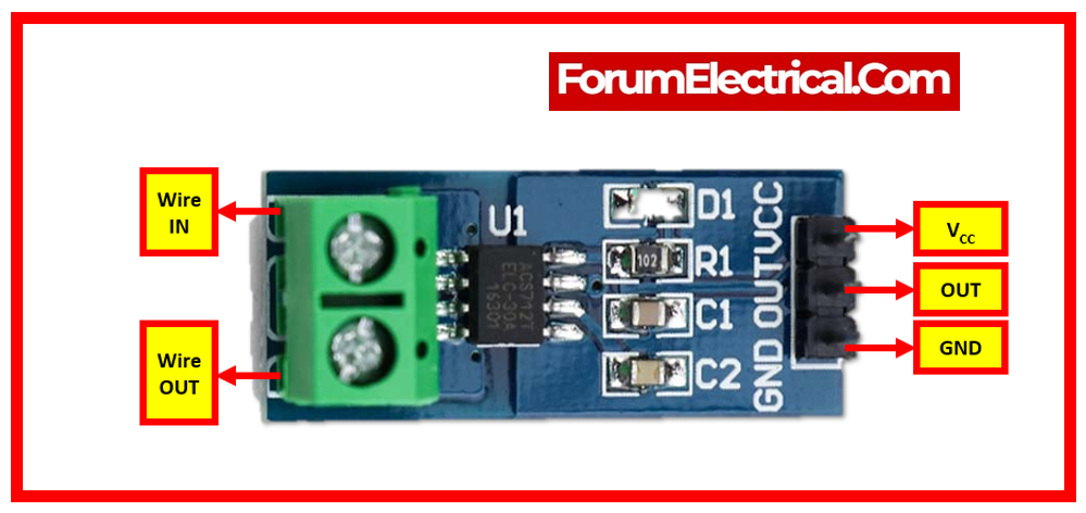
5). Current Sensor
A current sensor is a device that detects electrical current in a wire and produces a signal proportional to the current. The output signal can be analog, current, or digital.
6). Buzzer
A buzzer, often known as a beeper, is an audio signaling device that is either mechanical, electromechanical, or piezoelectric.
Buzzers and beepers are commonly used in warning systems, clocks, & to validate user input, such as mouse clicks or keystrokes.
A buzzer is commonly used in automobiles, domestic appliances like microwave ovens, and game shows.
It typically comprises of a number of switches (or) sensors coupled to a control unit.

Initially, the device was built on an electromechanical mechanism similar to an electric bell, but without the metal gong (which produces the ringing sound).
Another implementation with some AC-connected devices was to develop a circuit that converted the AC current into a loud enough noise to drive a loudspeaker and connected it to an 8-ohm speaker.
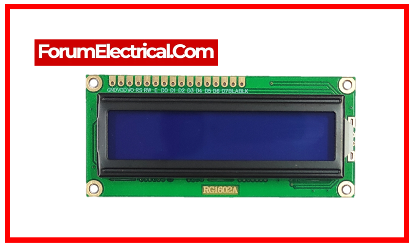
7). LCD Display
LCDs are often used to replace LEDs. This is for the following reasons: LCD prices are dropping. Having the capacity to display numbers, characters, & images.
This compares with LEDs, which can only display numbers and a few characters.
Incorporating a refreshing controller inside the LCD, which relieves the CPU of the burden of refreshing the display.
As a result, the LED must be updated by the CPU (or in another means) in order to continue displaying the data. Character and graphics programming made simple.
8). IC555
IC555 (555 timer integrated circuit) can be utilized in control circuitry to perform certain timed functions or generate pulses.
The 555 timer is a flexible integrated circuit used in timer, pulse generator, & oscillator applications.

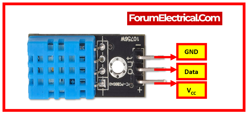
9). DHT Sensor
In a GSM-based Substation Monitoring and Control System, a DHT sensor (DHTxx, where xx indicates several types such as DHT11 or DHT22) is commonly used to monitor ambient conditions, specifically temperature and humidity. The DHT sensor is essential for giving real-time information on the substation’s ambient conditions.
10). Rectifier
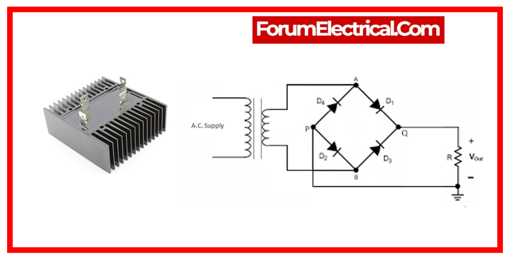
In a GSM (Global System for Mobile Communications)-based Substation Monitoring and Control System, a rectifier converts alternating current (AC) to direct current (DC).
11). Regulator

The regulator is essential to substation voltage stability. Regulators keep voltage output within tolerable limits. In electrical substations, constant voltage is essential for equipment operation and power distribution system reliability.
GSM (Global System for Mobile Communications) technology can remotely transmit regulator status and control information. This enables operators (or) monitoring systems view real-time regulator performance data, make modifications, and get alerts or notifications of problems. Remote monitoring & control improve substation efficiency, safety, and dependability.
12). LM 358 IC
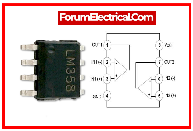
Operational amplifier (OP-AMP) integrated circuit LM358 has many electronics applications. GSM-based Substation Monitoring & Control Systems utilize the LM358 IC for signal conditioning or amplification.
GSM-based Substation Monitoring & Control Systems can use the LM358 IC for signal conditioning.
It can boost weak signals (or) convert them for processing. For instance, substation sensors can generate low-level signals which require amplification before entering the control system.
These signals can be amplified by the LM358 to fulfill monitoring & control circuitry input requirements.
Comparators and voltage level detectors can be made with the LM358 and other components.
This helps the monitoring & control unit make decisions based on substation sensor voltage levels and conditions.
To ensure accurate and dependable substation operational parameter monitoring and control, the LM358 IC in a GSM-based Substation
Monitoring & Control System may perform signal conditioning, amplification, or voltage level detection. Function depends on monitoring & control system design and requirements.
Software Requirements
1). Arduino IDE
GSM-based Substation Monitoring & Control Systems depend on the Arduino IDE. In such systems, the Arduino IDE programs the microcontroller, usually an Arduino board, that controls & monitors the substation.
2). Eagle
GSM-based Substation Monitoring & Control Systems use “Eagle” devices or modules to ensure system functioning. Eagles are typically used as GSM gateways or modules to transmit data.
The “Eagle” communicates real-time data between the substation & the central control system in a GSM-based Substation Monitoring & Control System. Remote monitoring, control requests, abnormal condition alarms, and seamless SCADA integration improve substation efficiency and dependability.
3). Proteus
Proteus functions as middleware in a GSM-based Substation Monitoring and Control System, allowing communication between the central system & substation devices. It supports
- Real-time data transmission,
- Remote monitoring,
- Control commands,
- Alerts,
- Data logging, and
- Security via GSM connectivity.
Proteus is essential for increasing the efficiency & reliability of substation operations.
Working
The ‘Substation Monitoring System’ project provides an innovative microcontroller-based system design.
It monitors the voltage, current, and temperature of a substation distribution transformer and protects the system against increasing values.
The objective is to continuously monitor electrical parameters to prevent distribution transformer burning due to overload, over temperature, and high voltage.
If any of these readings exceed the limit, an Electromagnetic Relay shuts down the equipment.
The relay activates when parameters surpass predefined thresholds. Relay acts as a circuit breaker to turn off main power. RF transmission sends immediate information to the intermediate station continually. GSM modems send real-time electrical parameters as SMS.
- Generation,
- Transmission, and
- Distribution
are needed to supply electricity.
Electric power is produced by nuclear, thermal, and hydraulic generators and transferred over high-voltage transmission systems.
The generator sends power to a transmission substation, wherein massive transformers convert it to 155kV to 765 kV for long-distance transmission (up to 300 miles).
Electric power distribution systems deliver power to users after transformers lower voltage. Distribution substations step-down power from the transmission grid to less than 11KV and provide commercial, residential, & industrial consumers via smaller distribution lines.
Monitoring and managing substations are crucial for providing clean power to consumers in this automated period.
Ageing distribution grids (substations) & lack of automated systems to monitor crucial conditions increase the risk of blackouts, brownouts, and fires.
Transformers, circuit breakers, relays, etc. make up substations. Overheating from transformer fluid leaks (or) insulation degradation causes failures.
The old method involves time-consuming, inaccurate manual system checks.
Rural substations are harder to monitor manually, thus taking action takes longer.
Substation automation solves all these issues. Current, temperature, & voltage are continuously measured by sensors.
The Arduino receives sensor outputs. Arduino is preprogrammed to notify the intermediate (or) primary station via GSM if parameters surpass a threshold.
Transformer receives 230V AC. transformer convert AC to AC voltage It converts 23V ac to 12-14V AC, which is supplied to the rectifier circuit, which converts ac voltage to DC voltage and outputs 12V DC. We need 12V for the relay & buzzer & 5V for the Arduino, so we use voltage regulator IC 7812 and 7805 to give us constant 12V and 5V.
A filter circuit removes output ripples. This project uses a DTH sensor to measure temperature.
It sends GSM SMS to approved person if temperature rises above specific level.
The LCD displays temperature, voltage, current, and frequency.
Current is minimal at 60W, but send SMS if load increases.
For frequency, we use LM358 IC and 555IC. 555 IC generates square wave with fixed frequency; therefore, we use pot to change frequency and lm358 for 50 HZ.
It creating a 50-Hz zero crossing circuit with LM 358 IC.
Buzzer will turn on and relay off if data exceeds specific level. all SMS data sent via GSM at that time RELAY on SMS sending to GSM turns relay on, and GSM sends command to Arduino, which sends command to GSM, which sends SMS to the relayed individual.
Loading SMS to GSM turns relay on, and GSM sends order to Arduino, which sends SMS to substation-on person.
If SMS is loaded off and sent to GSM, relay will be off, Arduino will transmit order to GSM, and GSM will send SMS to specific person that substation is off.
State SMS sending to GSM & Arduino sending instruction to GSM, GSM sends temperature, voltage, current, and frequency condition.
General Pin Functions
- LED: A built-in LED is powered by digital pin 13. The LED turns on when pin is high and off when it is low.
- VIN: The Arduin board’s input voltage when powered by an external source (rather than 5 volts via the USB connection or another regulated power source). This pin can be used to supply electricity or to access voltage provided by the power jack.
- 5V: This pin provides regulated 5V from board’s regulator. The board can be powered by the DC power jack (7-20V), the USB connector (5V), (or) the board’s VIN pin (7-20V). Using the 5V or 3.3V pins to supply power bypasses the regulator and may cause board damage.
- 3.3V: A 3.3-volt supply produced by on-board regulator. The maximum current draw is 50 mA.
- GND: Ground pins.
- I/O REF: Pin on Arduino board provides voltage reference for microcontroller operation. A properly constructed shield can read the IOREF pin voltage and choose the right power source, or it can activate voltage translators on outputs to work with either 5V or 3.3V.
- Reset: Add a RESET button to protects that obstruct the one on the board.
Special Pin Functions
The Uno’s 14 digital pins & 6 analog pins can all be used as inputs or outputs via the Pin Mode (), Digital Write (), & Digital Read () routines.
They run on 5 volts. Each pin may deliver or receive 20 mA under recommended operating conditions and contains a 20-50k ohm internal pull-up resistor (disconnected by default).
To avoid irreversible damage to the microcontroller, no more than 40mA should be applied to any I/O pin. The UNO features six analog inputs labeled A0 via A5, each with 10 bits of resolution (i.e., 1024 distinct values).
By default, they monitor from ground to 5 volts, but the AREF pin & the Analog Reference () function can be used to adjust the top limit of their range.
Furthermore, several pins have particular functions:
- Serial / UART pins: Serial / UART pins are 0 (RX) & 1 (TX). Utilized to receive (RX) & send (TX) TTL serial data. These pins are connected to the equivalent pins on the ATmega8U2 USB-to-TTL serial chip.
- Serial / UART pins 2 & 3: These pins can be set up to send an interrupt when a low value, a rising (or) falling edge, (or) a value change occurs.
- Pulse-width modulation (PWM): 3, 5, 6, 9, 10, & 11. The Analog Write () method supports 8-bit PWM output.
- Serial Peripheral Interface (SPI): 10 (SS), 11 (MOSI), 12 (MISO), and 13 (SCK). These pins enable SPI communication utilizing the SPI library.
- TWI (two-wire interface) / I²C: pins A4 (SDA) and A5 (SCL). Utilize Wire library to provide TWI communication.
- AREF (Analog Reference): The analog inputs’ reference voltage.
Result
The project titled “substation monitoring and controlling based on micro controller by using GSM modem” was created with the purpose of enabling equipment to be monitored and controlled from any location in the world by utilizing a GSM modem that is connected to a mobile phone.
Advantages of GSM based Substation Monitoring and Control System
1). Cost-effective design.
2). Real-time monitoring
3). Remote operation.
4). Provides instant feedback on device operation
5). Reduces power usage.
6). Devices may be operated via mobile and computer systems.
Disadvantage of GSM based Substation Monitoring and Control System
1). It is dependent on the network signal strength.
Applications of GSM based Substation Monitoring and Control System
1). This system has the possibility to be utilized in multiple fields of industry.
2). The home appliances may be monitored and controlled with the help of this system owing to its capabilities.
Conclusion
Using GSM, the system may deliver SMS via an intermediate station. This also reduces human labor while improving accuracy and reducing error, which led to the development of the ‘GSM based substation monitoring & control system’.
In the future, tapping of current can be examined using the same methodologies and techniques.