
- Introduction
- Standards
- Types of Circuit Breakers
- Conventional Testing Procedures
- 1). First Trip Test
- 2). Primary Injection Test
- 3). Contact Resistance Measurement
- 4). Dynamic Resistance Measurement (DRM)
- 5). Main Circuit Dielectric Test
- 6). Main Circuit Resistance Test
- 7). Auxiliary & Control Circuit Tests
- 8). Tightness Test
- 9). O-C Timing Test
- 10). Coil Resistance Test
- 11). Travel Test
- 12). Aesthetic Test
Introduction
Circuit breakers may not be the most noticeable types of equipment in a substation.
They spend a significant amount of time doing nothing except waiting in expectation.
However, there will come a time when the circuit breaker must operate properly and promptly.
Unfortunately, all electrically controlled devices will eventually malfunction, and if a circuit breaker fails to function properly, problems can cascade with potentially disastrous consequences.
However, testing allows technicians & substation managers to alleviate their concerns regarding circuit breaker functionality.
Circuit breakers protect equipment that is an essential component of the infrastructure and expensive to replace; keeping the breakers in good working order minimizes outages, which saves utilities & their customer’s time and money.
Furthermore, there is a genuine public service component to providing a consistent supply of power, avoiding corporate downtime and customer “dark” time. Substation breaker testing is a significant responsibility for all electricity companies.
The proper operation of a breaker is dependent on several distinct components that need to be calibrated & tested on a regular basis.
The parameters used to establish maintenance intervals vary widely amongst power utilities, although they frequently include time since the last test, number of operations, and the extent of fault current activities.
Environmental factors like as humidity and temperature – either the breaker is situated in a desert (or) coastal region – also influence the repair timetable.
Standards
International standards define the design and functioning of high voltage circuit breakers, as well as their type and routine tests.
IEC 62271-SER ed1.0 – High-voltage switchgear & control gear.
ANSI/IEEE C37– Guides & Standards for Circuit Breakers, Relays, Switchgear, Substations, and Fuses.
Types of Circuit Breakers
Circuit breakers can be classed in a wide range of ways, including voltage, application, insulating medium, etc.
Depending on where a circuit breaker is located in the power network, it will require varying levels of reliability.
These standards usually determine the breaker’s testing schedule and the quantity of maintenance it will obtain.
The various types of high voltage circuit breakers comprise the following:
- Oil Circuit Breaker
- Air Circuit Breaker
- Vacuum Circuit Breaker
- SF6 Circuit Breaker
Conventional Testing Procedures
A circuit breaker’s primary functions include opening the circuit in reaction to faults and connecting/disconnecting objects & parts of the electrical network.
Normal-load operations account for the vast majority of circuit breaker switching operations.
Initially, a circuit breaker may appear to have nothing to test, but a closer look shows an advanced system that must function flawlessly in milliseconds.
One of the most important purposes of circuit breaker testing is to measure those milliseconds, also known as main contact timing.
Furthermore, contact movement is nearly always measured as part of the circuit breaker maintenance and service schedule.
In this post, we will look at the most prevalent test methods for breakers as well as some new techniques that are quickly acquiring widespread acceptance.
1). First Trip Test
A circuit breaker’s initial open operation after a long idle period is a good indicator of its condition.
This test involves connecting and measuring the circuit breaker while it is in service.
No test connections are established outside the control cabinet.
The main benefit of a first trip test is to test circuit breaker functioning in “real world” circumstances.
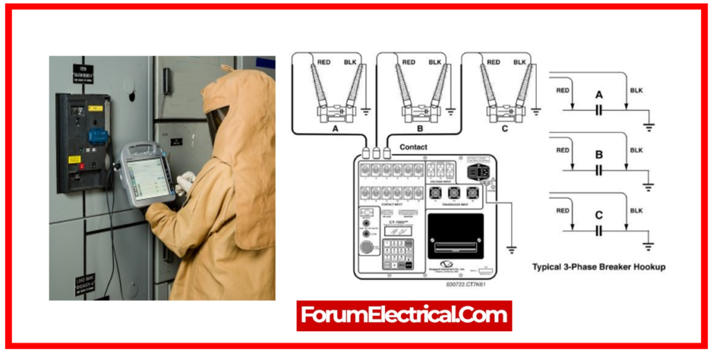
First trip testing will show if the circuit breaker has slowed due to rust or dried grease in mechanism linkages (or) coil armatures.
Traditional alternative test techniques require the circuit breaker to be removed from operation and operated at least one time.
A first trip test on a gang-operated circuit breaker measures one-coil current.
However, an independent pole-operated breaker measures three coil currents. Analysis of coil current signatures reveals circuit breaker state. We can also measure auxiliary contact timing.
The secondary current in the protective CTs can be monitored to determine the circuit breaker’s opening time, but the arcing time is included.
Since parallel primary current paths limit arcing, opening time can be more accurately estimated.
First trip analysis can indicate the following problems:
| Problem | Identified By |
| The system includes sticky trip latch components. | Trip coil current The graphical representation comparison. |
| Delayed travel or close initiations. | Auxiliary contact timing measurement. |
| Issues with power supply to the circuit breaker. | Coil voltage graph. |
| Sluggishness in energy transfer via a spring, hydraulic, or pneumatic operating mechanism. | Speed measurement based on motion graph. |
| Loose connections in control wire. | Comparison of trip and near coil current graphs. |
Main Contact Timing
Main contact timing follows IEC definitions:
- The opening time is the time between activating the trip coil and the arcing contacts separating at all poles.
- The closing time is the period from activation of the closing device (such as the coil) until the moment the arcing contacts touch in all poles.
The primary contact timing test ensures circuit breaker manufacturer-specified opening and closing times.
Timing outside manufacturer guidelines, especially when switching short-circuit currents, increases arcing time. This causes severe contact wear and equipment emergencies such contact melting.
If contacts melt, the breaker must be repaired or replaced.
Correct synchronization between phases and, if there are many breaks / phases, across contacts in the same phase is essential, as are circuit breaker opening and closing times.
Multiple contacts in sequence require phase synchronization. When a breaker opens a circuit, it divides voltage. Too great a time gap between contact operations will cause high voltage across one, causing flashover and perhaps damaging the breaking chamber.
A 3-phase system power transmission system at 50 Hz has a higher tolerance for phase simultaneity as there is typically 3.33 ms across zero crossovers.
However, in such systems, time tolerance is frequently less than 2 ms. In both cases, synchronized switching breakers must meet stricter requirements.
IEC 62271-100 specifies circuit breaker synchronization to be better than 1/4 cycle for shutting and 1/6 cycle for opening. Better than 1/8 cycle synchronization across interrupters in the same phase.
Resistor Contact Timing
Resistor contacts may be pre- or post-insertion. Timing of resistor contacts is done simultaneously with main contacts, but only when main contacts are open can they be detected. Resistance is a good evaluating measure.
Auxiliary Contact Timing
The time connections between primary and auxiliary contacts are not limited, but understanding and checking auxiliary contact operation is essential. Auxiliary contacts close and open circuits.
To prevent coil burnout, such a contact could enable a closing coil whenever a breaker is ready to close and open the circuit shortly after. Relay protection and signalling use auxiliary contacts.
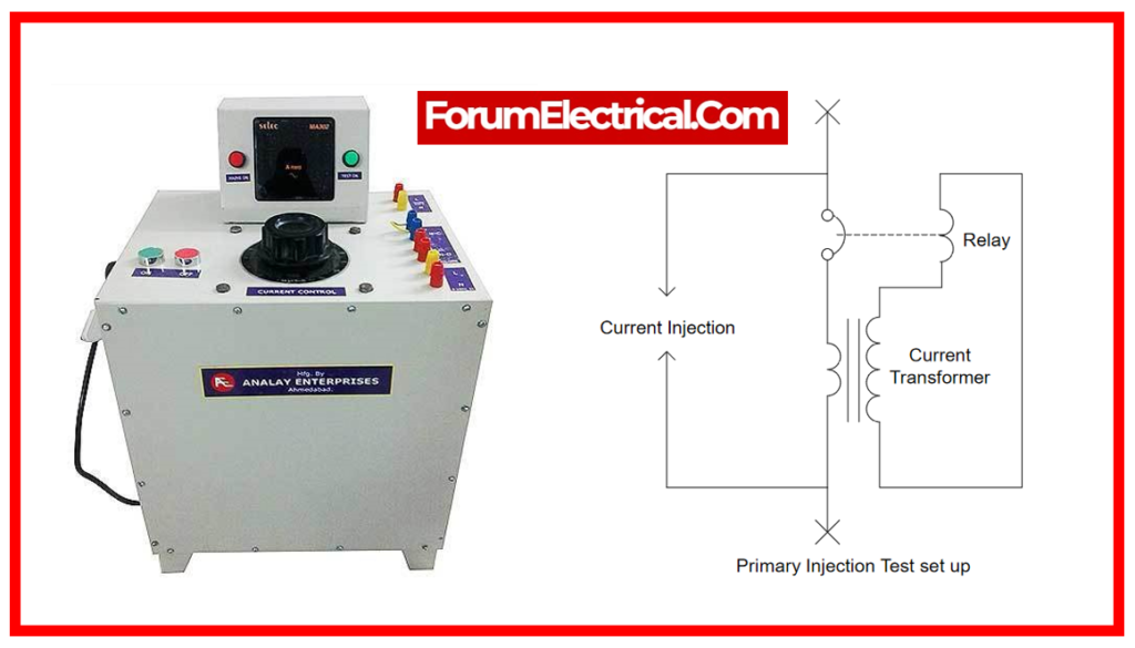
2). Primary Injection Test
For primary injection testing, a large current is injected into the primary side of the transformer.
The test covers the full chain, which includes the
- Current transformer,
- Wires,
- Connection points,
- Relay protection, and
- Circuit breakers (in some cases).
During primary injection testing, the system undergoing test must be shut down.
This type of test is normally carried out as part of commissioning process.
The only method to ensure that a direct low voltage circuit breaker works properly is to run a strong current through it and observe/record the results.
Main Contact Motion
A high-voltage breaker is intended to stop short-circuit currents in regulated manner.
This places considerable pressure on the mechanical functionality of the operating mechanism & all of the components in the interrupter chamber.
The breaker must operate at a specific speed in order to provide enough pressure for the cooling stream of air, oil, or gas (depending on the kind of breaker) to extinguish the arc formed after contact separation till the next zero crossing.
It is essential to cut off the current to avoid a restrike. This is accomplished by making sure the contacts are adequately separated prior to the moving contact reaching the so-called damping zone.
The arcing zone is the distance required to extinguish the breaker’s electric arc. From the motion curve, velocity & acceleration curves may be derived, revealing even minor changes in the breaker mechanics.
The contact motion is collected by connecting a travel transducer to the moving element of the working mechanism. The transducer generates an analogue voltage in response to the movement of the contact.
Motion is typically represented as a time vs distance curve.
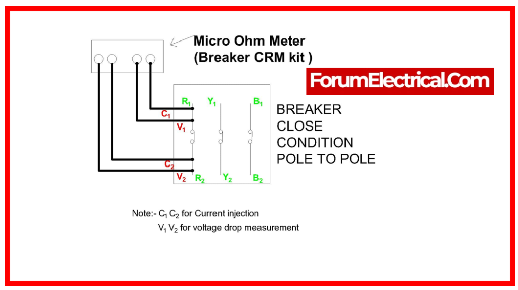
3). Contact Resistance Measurement
When the circuit breaker is closed, a known DC current is injected via the main contact system to determine contact resistance.
By monitoring the voltage drop, the resistance may be estimated. The value of main contact resistance represents the state of the conducting components. This test is often referred to as static resistance measurement (SRM).
The static resistance value serves as a reference value for all electrical connections and joints. According to IEC56, this resistance should be measured with a current ranging from 50 A to the breaker’s nominal current.
ANSI C37.09 requires a minimal test current of 100 A.
Many international & national standards establish comparable guidelines to prevent the danger of receiving incorrectly high values if the test current is excessively low.
Heat created by a high test current can disperse contact grease residues or other contaminants found on contact surfaces.
When the circuit breaker contacts are in bad condition, the results can differ significantly from those recorded at the factory while the breaker was new.
ANSI specifies a 200% increase in resistance over the highest value specified by the factory.
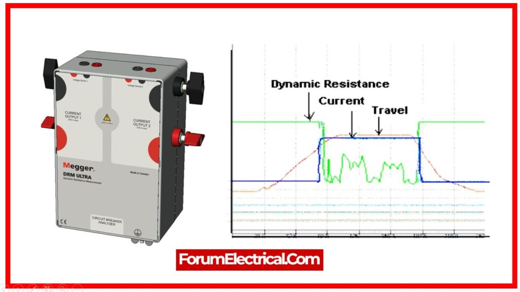
4). Dynamic Resistance Measurement (DRM)
This test is performed by injecting DC current via the breaker’s main contacts and monitoring both the voltage drop & current when the breaker is operational.
These values are subsequently utilized to depict resistance versus time. If contact movement is captured at the same time, the resistance of each contact position can be calculated.
This method is mostly used for contact diagnostics, while it can also be utilized for main contact timing. The only way to determine the total length of arcing contact is to disassemble the circuit breaker.
In SF6 breakers, the arcing contact is often constructed of tungsten. This contact gets burned off & gets shorter with each interruption of the load current. The arcing contact’s shortening is plainly seen from dynamic resistance tests.
To obtain valid DRM data, large test current and test equipment with adequate voltage measurement resolution are necessary.
Electrical Tester, will cover further widely used circuit breaker tests such as coil and voltage tests; vacuum bottle, SF6 leakage, & air pressure tests; & new test methods, like as resonant frequency techniques, which are rapidly gaining popularity.
5). Main Circuit Dielectric Test
This test, also known as the ‘Dielectric Withstand Test’, is designed to assess the CB’s withstand capacity against a variety of power frequencies & impulse voltages.
As standard procedure, a dry, high-power frequency voltage test must be performed for 60 seconds. According to the IEC 60061-2 standard, the voltage delivered should be 1.5 – 1.8 times higher than the CB’s rated voltage in a frequency range of 45 to 65 Hz.
Alternatively, unless otherwise indicated by the relevant technical committee, the ideal test voltage levels should be sustained within ±1% of the required level during the test.
For tests lasting more than 60 seconds, maintain voltage readings within ±3% of the required level.
6). Main Circuit Resistance Test
The IEC 62271-100 standard requires a minimum current of 50 amps across the CB. The DC millivolt drop across it should be measured to determine the main contact resistance value using the Kelvins 4-Wire concept.
The main contact resistance value cannot go above 150 micro ohms.
7). Auxiliary & Control Circuit Tests
Auxiliary & control circuits are usually tested using three distinct tests:
- Inspection & verification to establish whether the auxiliary & control circuits comply with the specified Circuit and Wiring Diagrams.
- Functional testing of all (LV) low-voltage circuits to check if auxiliary & control Circuits are functioning seamlessly with the other elements of the switchgear and control gear,
- Visual inspection to see if the auxiliary & control circuits may be securely accessed without also risking an electric shock from direct contact with the main circuit.
8). Tightness Test
Manual testing should be performed to determine the tightness of CB’s connections.
Depending on the kind of switchgear, the following three tightness checks should be performed:
- Controlled & closed-pressure tests for the gas-insulated switchgear.
- Sealed-pressure tests for gas-insulated & vacuum-insulated switchgear.
- Perform a liquid tightness test to find any leaks.
9). O-C Timing Test
When it comes to avoiding an electrical accident, the opening & closing time of CB are important.
In case of an electrical fault, the CB must quickly open and trip the current, then close when the issue is resolved.
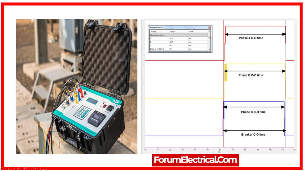
Industry best practices indicate that HV CBs open (& trip) between 30 to 50 ms of fault happening and shut between 60 to 80 milliseconds of the fault being fixed.
However, if the fault persists even after CB has closed, it should reopen, re-trip the current, and then close again. Unpredictable conditions like these make testing the CB’s Opening-Closing (O-C) timings essential.
10). Coil Resistance Test
CBs have dedicated coils for the opening and shutting. Depending on the condition, the relay delivers a ‘coil current’ that activates and operates the relevant coil.
To make sure whether a CB continues to function properly, measuring the resistance levels of each coil is essential.
11). Travel Test
Every CB’s interrupter has two mechanisms:
- Fixed and
- Movable.
As a CB closes, the moving part moves towards the fixed component, completing the loop.
To make sure that both of these components function properly, travel tests are conducted to assess their effectiveness. There are four basic characteristics to consider while performing trip tests:
Stroke Length: The contacts’ total travel distance from where they are at rest in a given state. For example, in a closed state, the distance travelled from resting posture to open state, & vice versa.
Damping: This is determined directly on the trip curve by computing the velocity in the damping zone or the time between two predetermined places on the travel curve in the damping zone.
Contact Wipe: The total length measured from initial contact touch to final resting posture following the relevant procedure.
Over-Travel: Over-travel, as measured directly from the travel curve, is the maximum displacement which the contacts may achieve beyond their resting position.
Rebound: The lowest displacement (after over-travel) to the contacts’ final resting position.
12). Aesthetic Test
Aesthetic tests, which are as significant and involve a thorough inspection of the switchgear & control gear to ensure compliance with their individual procurement requirements.
These tests include a thorough examination of the language and information used on the respective nameplates, the identification of any auxiliary equipment, the color and quality of the paint and corrosion-protection materials used on metallic surfaces, & the values of the resistors & capacitors connected to main circuit.
