
In modern high voltage (HV) and extra high-voltage (EHV) power transmission systems accurate voltage measurement is the most important one of reliable operation.
Whether for protection signals, energy metering (or) power system synchronization, voltage sensing equipment accuracy & reliability determine grid stability.
Conventional electromagnetic Voltage Transformers (VTs) are primarily for distribution and subtransmission voltage levels.
However, as system voltages rise above 132 kV these devices become prohibitively large, expensive and impractical due to the insulation requirements imposed by the high working voltage.
The Capacitive Coupled Voltage Transformer (CCVT) or (CVT) was developed specifically to address this. By utilizing a capacitive voltage divider to reduce the high primary voltage to an intermediate level prior to applying electromagnetic transformation CCVTs provide an elegant, economical and technically superior solution for HV and EHV substations.
CCVT are the global standard for transmission networks above 132 kV.
What is a CCVT?
A Capacitive Coupled Voltage Transformer (CCVT) is a specialized instrument transformer that steps down very high system voltages to standardized secondary voltages that is typically 110 V or 63.5 V (phase-to-neutral) which is suitable for use by
- Protection relays,
- Metering equipment and
- SCADA systems.
CCVTs reduce voltage capacitive instead of using electromagnetic induction like standard VTs.
This makes it vastly more practical & cost effective at EHV levels where the cost & size of a fully electromagnetic device would be enormous.
In addition to voltage measurement and protection signaling CCVTs uniquely support Power Line Carrier Communication (PLCC) allowing high frequency signals (typically 30 – 500 kHz) to be injected onto the transmission line for
- Protection,
- Telecontrol and
- Voice communication purposes.
This dual functionality makes the CCVT an indispensable asset in modern transmission substations.
Components of a CCVT
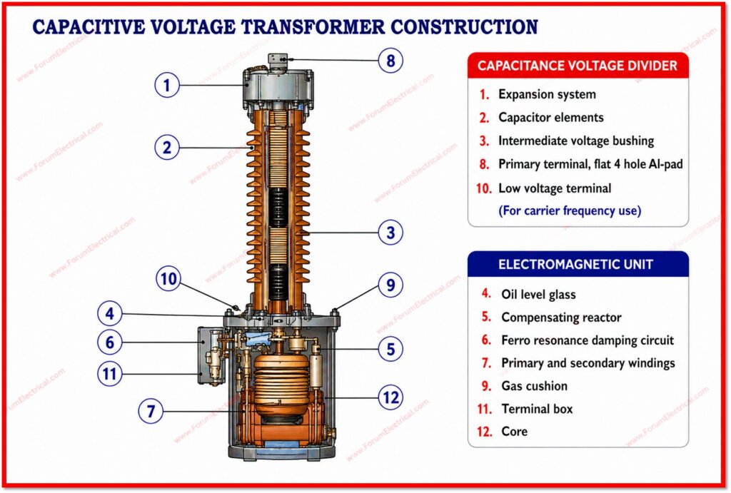
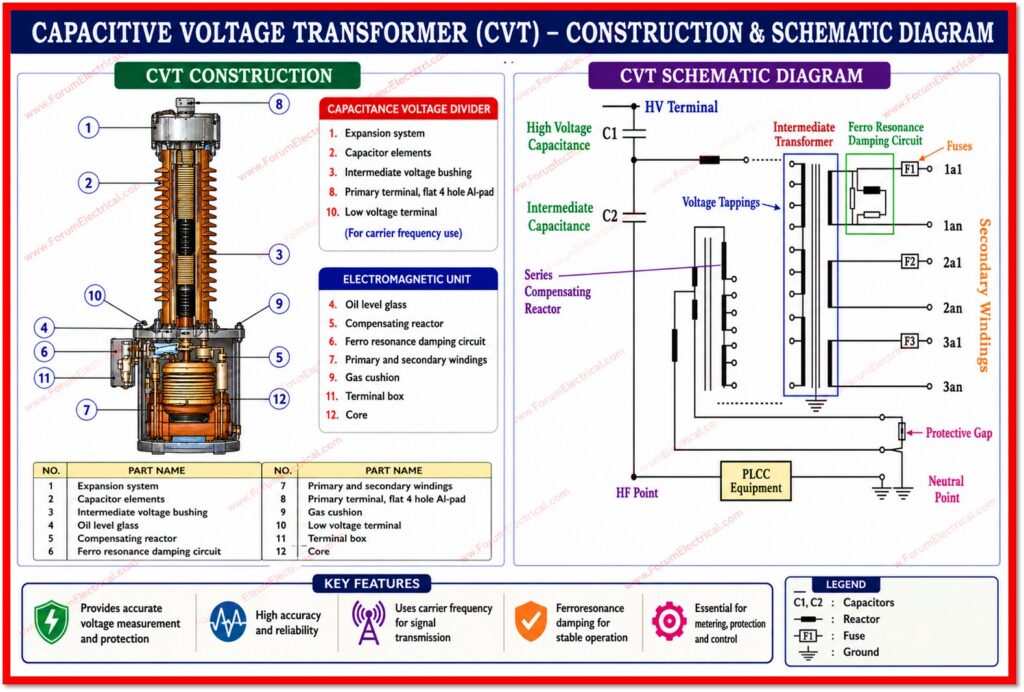
A CCVT consists of 4 principal sub-assemblies each performing a distinct and essential function.
| Component | Description | Function |
|---|---|---|
| Capacitive Voltage Divider (C1 & C2) | Stack of accurate high voltage capacitors connected in series between line terminal & ground | EHV is reduced to an acceptable intermediate voltage (typically 5 -15 kV) in proportion to capacitance ratio C2/(C1+C2) |
| Intermediate Electromagnetic Transformer (EMT) | Oil immersed, iron core transformer housed in the base tank | Further steps down the intermediate voltage to the standard secondary output (110 V / 63.5 V) |
| Ferro resonance Suppression Circuit (FSC) | Passive damping network like resistor, reactor (or) active circuit connected to the secondary | Eliminates ferro resonance oscillations that can cause large overvoltages & relay maloperation |
| Secondary Terminal Box (STB) | Weather proof metallic enclosure at the base | Houses secondary terminals, burden connections, earthing links & PLCC coupling components |
Capacitive Voltage Divider
The capacitive divider is the defining element of the CCVT.
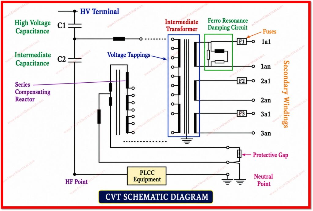
It consists of a high voltage (HV) capacitor C1 in series with a lower voltage capacitor C2.
The line terminal is connected to the top of C1 while C2 connects C1 to ground.
The output tap is taken across C2. The intermediate voltage at this tap is given by
Vintermediate= Vline x C2 / (C1 + C2)
The capacitor stack is housed in a tall porcelain or composite insulator column filled with dry nitrogen (or) oil for insulation.
The number of capacitor discs increases with voltage level making the column taller as the system voltage rises.
Intermediate Electromagnetic Transformer
The electromagnetic unit (EMU) sits at the base of the CCVT and receives the intermediate voltage from the capacitive divider that is typically in the range of 5 kV to 15 kV.
Its primary winding is tuned with a series inductance (compensating reactor) to resonate with the capacitive divider at system frequency (50 Hz / 60 Hz), thereby compensating for the capacitive reactance & improving accuracy.
To measure and protect, the secondary winding generates 110 V (line-to-line) / 63.5 V (phase-to-neutral).
Ferro-resonance Suppression Circuit
Ferro-resonance occurs between the EMUs saturable iron core and the dividers capacitance.
Left unsuppressed ferro-resonance can generate sustained overvoltages on the secondary which is potentially causing
- Relay maloperation,
- Equipment damage and
- Erroneous tripping.
The ferro resonance suppression circuit damps these oscillations rapidly.
Modern CCVTs employ passive resistor type FSCs for simplicity & reliability while more sophisticated designs utilize active electronic damping.
Working Principle
The operating sequence of a CCVT can be understood in 3 different stages:
Stage-1: Capacitive Division
The full line-to-ground voltage (e.g., 220 kV / √3 ≈ 127 kV) is applied across the series combination of C1 & C2.
The voltage divides inversely proportional to capacitance generating a manageable intermediate voltage across C2.
Stage-2: Electromagnetic Transformation
The intermediate voltage is applied to the primary of the EMU.
The compensating reactor in series with the primary tunes the circuit to system frequency that is cancelling the capacitive reactance.
The EMU then transforms this intermediate voltage down to the standard secondary level (110 V or 63.5 V).
Stage-3: Secondary Output
The secondary output is fed to the secondary terminal box where it is distributed to
- Protection relays,
- Energy meters,
- Synchronising equipment and
- SCADA.
PLCC coupling equipment if present injects carrier signals via the CCVT onto the transmission line.
The entire assembly is designed so that the secondary voltage accurately that represents the primary line voltage across the full burden range within the accuracy class specified by IEC 61869-5 (formerly IEC 60044-5) (or) equivalent standards such as ANSI/IEEE C93.1.
Why CCVT is preferred at High Voltages?
| Parameter | Conventional VT | CCVT |
|---|---|---|
| Capital Cost at EHV | Very High insulation cost rises steeply with voltage. | Moderate and capacitive stack is cost-effective at high voltages. |
| Physical Size & Weight | Extremely large at 220 kV & above. | Compact & manageable column design. |
| PLCC Capability | Not available | Integral and line-to-PLCC coupling built in. |
| Insulation Coordination | Full insulation required on primary winding. | Capacitor stack inherently handles EHV and EMU is at intermediate voltage. |
| Transient Response | Excellent and no transient error. | May exhibit transient ferroresonance and is managed by FSC. |
| Accuracy Class | 0.1 to 1.0 (IEC) | 0.2 to 3P (IEC 61869-5) |
| Typical Application | Up to 66 kV & 132 kV | 132 kV & above (220 kV, 400 kV, 500 kV & 765 kV) |
Accuracy Classes & Standards
CCVTs are classified by accuracy class per IEC 61869-5 for both metering & protection applications
- Metering cores: Class 0.2 or Class 0.5 that is high accuracy required for energy billing.
- Protection cores: Class 3P or Class 6P that is must maintain adequate accuracy during fault conditions.
- Combined units may include both metering & protection secondary windings
Ratio error (voltage error) & phase displacement (phase error) must stay within class limits for the specified burden & voltage range (80% to 120% of the rated voltage for metering & 5% to 173% for protection).
Practical Importance in Power Systems
The reliability of a CCVT has direct & far reaching consequences for the substation protection and also metering performance
Distance Protection
Distance relays calculate the impedance to a fault using a measured voltage and current.
An inaccurate (or) transient affected CCVT output may cause a distance relay to under reach (or) over reach leading to incorrect (or) failed fault clearance.
Over/Under Voltage Protection
Voltage magnitude measurements directly drive overvoltage & undervoltage protection functions.
CCVT accuracy is essential to avoid spurious operation (or) failure to detect genuine voltage excursions.
Synchronization
Before closing a circuit breaker to parallel 2 sections of a network and synchronism check relays verify that voltage, frequency and phase angle on both sides are within acceptable limits.
CCVT phase accuracy is critical for this function.
Energy Metering
For grid-connected generators, industrial consumers & inter-utility exchange points, energy metering accuracy directly determines the billing & settlement.
CCVT ratio & phase errors should comply with revenue grade accuracy classes.
Power Line Carrier Communication (PLCC)
In transmission networks lacking specialized fiber optic communication, PLCC is the main route for pilot protection schemes, telecontrol and voice.
The CCVT serves as the coupling interface across the carrier equipment & the transmission line.
Traction & Grid Substations
Maintenance and Testing
Periodic maintenance of CCVTs is essential to ensure continued accuracy & reliability.
Typical maintenance activities include:
- Capacitance & power factor (tan delta) monitoring of capacitor stack to detect insulation degradation.
- Secondary voltage ratio check to verify accuracy against a reference standard.
- Insulation resistance measurement to check for moisture ingress (or) insulation deterioration.
- Ferro-resonance suppression circuit function test to confirm the FSC is correctly damping any oscillation.
- Oil-filled systems use oil sampling and DGA to detect internal defects and dielectric degradation.
- Inspection of porcelain/composite housing is for cracks, contamination (or) damage.
Maintenance intervals are typically specified by the manufacturer yet are commonly performed every 3 to 5 years for major tests with visual inspection annually.
Conclusion
The Capacitive Coupled Voltage Transformer (CCVT) is a fundamental and indispensable instrument in modern high voltage (HV) transmission substations.
By combining the insulation economy of capacitive voltage division with the transformation accuracy of an electromagnetic unit the CCVT provides a practical, reliable and cost effective solution for the voltage measurement, protection, metering & communication at voltages where the conventional electromagnetic VTs are no longer viable.
The correct selection, installation & maintenance of CCVTs is essential not only for the accuracy of individual protection & metering functions but for the overall stability and reliability of transmission network.
CCVT remains a key technology for power engineers as power systems increase in voltage and complexity.

, their construction, working principle, advantages, applications and function in high voltage transmission system voltage measurement and protection.)