
- What is a Generator?
- What is DC Generator?
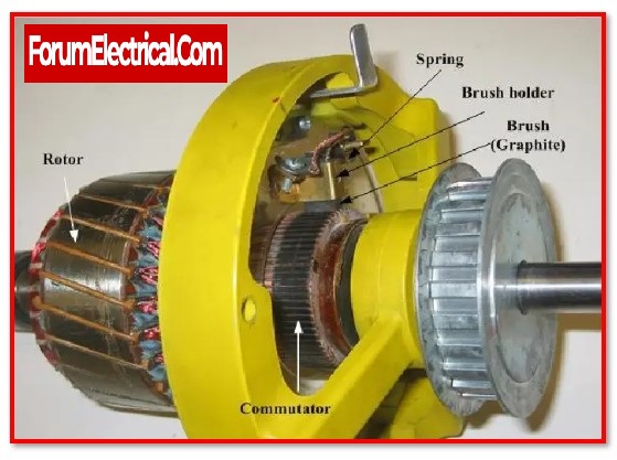
- Construction of DC Generator
- Commutator Function of a DC Generator
- Working Principle of a DC Generator
- E.M.F. Equation of a DC Generator
- Efficiency of the DC Generator
- DC Generator Losses
- Characteristics of DC Generator
- Types Of a DC Generator
- Advantages of DC Generator
- Disadvantagesof DC Generator
- Applications of DC Generator
- Difference between AC Generator and DC Generator
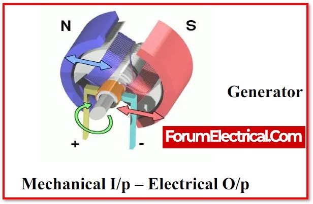
A DC generator is a device that generates electrical energy. This device’s primary purpose is to convert mechanical energy into electrical energy. Mechanical energy sources include
- Hand cranks,
- Internal combustion engines,
- Water turbines,
- Gas and steam turbines, and
- Wind turbines.
The generator powers all of the electrical power networks. An electric motor may perform the generator’s reverse function. The motor’s primary function is to convert electrical energy to mechanical energy. Motors and generators have many characteristics. This post gives a brief overview to DC generators.
What is a Generator?
Electric Generators are devices that convert mechanical energy into electrical energy. The produced electrical energy is then transferred & distributed through power lines for household and commercial usage. Generators are classified into two types:
- AC (alternating current) generator
- DC (direct current) generator
An AC generator is a device that transforms mechanical energy into alternating current electricity.
A direct current generator (DC generator) is a kind of electrical generator that transforms mechanical energy into direct current electricity.
What is DC Generator?
A DC generator, also known as a direct current generator, is a kind of electrical equipment whose primary function is to convert mechanical energy into direct current electricity.
The concept of energetically generated electromotive force is used in the energy alteration process.
As a conductor cuts magnetic flux, it generates energetically induced electromotive force based on Faraday’s Laws’ Electromagnetic Induction principle.
This electromotive force has the potential to create a current flow even when the conductor circuit is not opened.
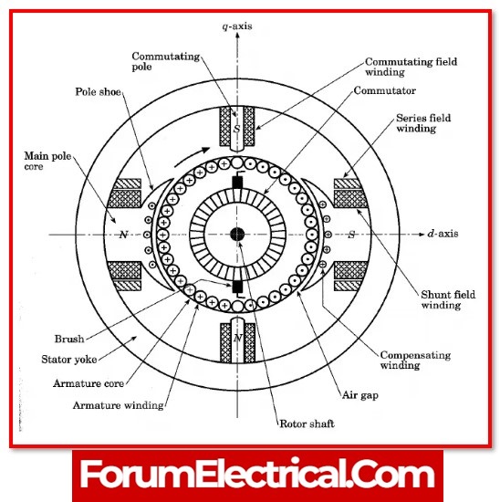
Construction of DC Generator
A DC generator may also be utilised as a DC motor without modifying its design.
As a result, a DC motor or a DC generator might be referred to as a DC machine.
DC generator is made up of various components, including
- Yoke,
- Poles
- Pole shoes,
- Field winding,
- Armature core,
- Armature winding,
- Commutator, and
- Brushes.
However,
- Stator and
- Rotor
are the two most important components of this device.
1). Stator
The stator is a crucial component of the DC generator, & its primary role is to generate magnetic fields in which the coils spin.
These has stable magnets that have two reverse poles that are positioned in a way that faces each other.These magnets are positioned in the rotor region.
2). Armature Core or Rotor
The rotor, also known as the armature core, is the second most important component of a DC generator.
It is made up of slotted iron laminations (laminated) with slots that are stacked to form a cylindrical armature core.
In general, these laminations are provided to reduce eddy current losses.
3). Armature Windings
The armature core slots serve primarily to retain the armature windings.
They are wound in a closed circuit and linked in series to parallel to increase the total of the generated current.
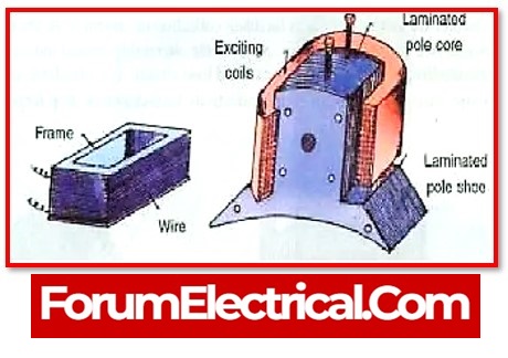
4). Yoke
The exterior structure of the DC generator is called a Yoke, and it is built of cast iron or steel.
It provides the mechanical power required to convey the magnetic flux provided by the poles.
5). Poles
They are mostly used to secure the field windings.
These windings are typically coiled on the poles and are linked in series or parallel by the armature windings.
Also, the poles will provide a link towards the yoke utilising the welding technique rather than screws.
6). Pole Shoe
Pole shoe is largely for dispersing the magnetic flux & preventing the field coil from dropping that the pole shoe is utilised.
7). Commutator
The commutator functions similarly to a rectifier in that it converts AC electricity to DC voltage inside the armature winding before passing it over the brushes.
It is created with a copper segment, and each copper segment is shielded from the others by mica sheets. It is situated on the machine’s shaft.
8). Brushes
Brushes are used in the process of establishing and maintaining electrical connections between the commutator & the load circuit that is external.
Commutator Function of a DC Generator
The commutator’s main function is to convert AC to DC. It functions as a reversing switch.
The emf induced inside the generator’s armature coil is alternating. As a result, the current flowing through the armature coil might also be alternating current.
When the armature coil passes the magnetic unbiased axis, this current may be reversed via the commutator at the accurate moment.
As a result, the load obtains a DC or unidirectional current.
The commutator ensures that current from the generator flows in just one way permanently.
By moving on the commutator, the brushes will establish high-quality electrical connections between the generator and the load.
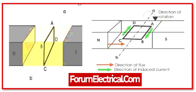
Working Principle of a DC Generator
An electric generator operates on the principle of the faradays law of electromagnetic induction, which states that whenever a conductor is placed in a moving magnetic field, an e.m.f is induced in the conductor, causing a current to flow in the conductor, provided the circuit is closed.
An electromotive force, or emf, is said to be induced in a conductor in accordance with the laws of electromagnetic induction that were developed by Michael Faraday.
These laws state that an emf is said to be induced in a conductor whenever the conductor is either positioned within a magnetic field that is changing or moved within a magnetic field.
The emf equation for a DC generator may be used to compute the magnitude of the induced emf in a circuit. If the conductor is connected to a circuit that is completely closed, the induced current will flow only inside the circuit.
The armature conductors of a DC generator are spun into the field that is produced by the field coils, which are responsible for creating the electromagnetic field.
Hence, an electromagnetically induced emf is produced inside the armature conductors of the generator.
Using Fleming’s right hand rule, can determine the flow of the induced current.
E.M.F. Equation of a DC Generator
According to Faraday’s Laws of Electromagnetic Induction, the emf equation of a dc generator is
Eg= PØZN/60 A
Where,
Φ – flux (or) pole within (Webber)
Z – Total number of armature conductor
P – Number of poles in a generator
A – Number of parallel lanes (within armature)
N – Rotation of armature inrevolutions per minute (r.p.m)
E – Induced e.m.f (any parallel lane) within the armature
Eg– Generated e.m.f(any one of parallel lanes)
N/60 – Number of turns per second
dt = 60/N sec – Time for one turn
Efficiency of the DC Generator
DC generators are very dependable, with efficiency ratings ranging from 85 to 95%.
Consider the following generator output: VI
A generator’s input is VI + Losses.
Losses = I2aRa + Wc
Input = VI + I2aRa + Wc
If the shunt field current is negligible,
Ia = I (approx)
Following that,
n = VI/ (VI+Ia2Ra+Wc)
n = 1/(1+IRa/V+Wc/VI)
For maximum efficiency, d/dt (IRa/V+Wc/VI) = 0, else I2Ra = Wc.
As a result, efficiency is greatest once variable loss equals constant loss.
The load current with the maximum efficiency is I2Ra = wc, else, I = √Wc/Ra.
DC Generator Losses
There are several types of machines that are available where the complete input energy cannot be converted into output due to input energy loss. As a result, various losses may occur in this sort of generator.
1). Copper Loss
In armature copper loss (Ia2Ra),
Where,
Ia –Armature current and
Ra– Armature resistance.
For shunt-wound generators, the field copper loss is comparable to Ish2Rsh, which is almost steady.
For series wound generators, the field copper loss is identical to Ise2Rse, which is likewise almost steady.
For compound-wound generators, the filed copper loss is comparable to Icomp2Rcomp, which is likewise almost steady.
Copper losses reach 20-30% in full load losses due to brush contact.
2). Core (or) Iron (or) Magnetic Loss
Core losses may be divided into two categories:
- Hysteresis Loss and
- Eddy current Loss.
Hysteresis Loss
This loss is mostly caused by the armature core reversal. Every component of the rotor core alternately passes under the two poles, north and south, and achieves S and N polarity.
When the core supplies fall below one set of poles, the core will complete one series of frequency reversals.
Eddy Current Loss
The armature core slices the magnetic flux throughout its rotation, and e.m.f. may be induced inside the core’s exterior; based on electromagnetic induction principles, this emf is incredibly small, but it generates a high current in the core’s surface.
This massive current is referred to as eddy current, and the loss is referred to as eddy current loss.
Since field currents in compound and shunt generators are almost steady, core losses are stable.
This loss happens in full-load losses at a rate of 20% to 30%.
3). Mechanical Loss
Mechanical loss is defined as the air friction (or) windage losses of a revolving armature.
Friction loss accounts for 10% to 20% of full load losses at bearings and commutators.
4). Stray Loss
Stray losses are mostly caused by the combination of core and mechanical losses. These losses are also known as the rotational losses.
Characteristics of DC Generator
The DC generator’s characteristic may be described as the graphical depiction of the two discrete values. This graph will display the steady-state features that explain the major relationship between the terminal voltage, loads, and excitation. The most key characteristics of DC generator are mentioned below.
- Magnetization Characteristics
- Internal Characteristics
- External (or) Load Characteristics
1). Magnetization Characteristics
The magnetization characteristics distinguish between creating voltage and producing no-load voltage through field current at a constant speed. This kind of characteristic is sometimes referred to as an open circuit or no-load characteristic.
2). Internal Characteristics
The internal characteristics of the dc generator can be shown against the load current & generated voltage.
3). External (or) Load Characteristics
The load (or) external type characteristics define the primary relationships between load current and terminal voltage at a constant speed.
Types Of a DC Generator
There are primarily two types of DC generators, namely,
1). Separately Excited DC Generator and
2). Self-ExcitedDC Generator.
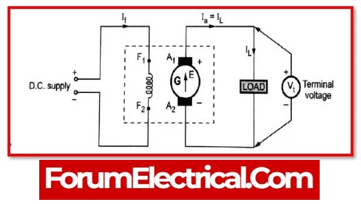
1). Separately Excited DC Generator
In this type, the field coils get their energy from a separate DC source that is located outside the magnet itself.
2). Self-Excited DC Generator
The current that is created by the generator itself is used to provide power to the field coils in this sort of generator.
The presence of residual magnetism in the field poles is the cause of the initial generation of emf.
The electromagnetic field (emf) that is generated is responsible for the flow of certain current in the field coils, which in turn increases the field flux & the quantity of emf that is generated.
Self-excited DC generators are further classified as follows:
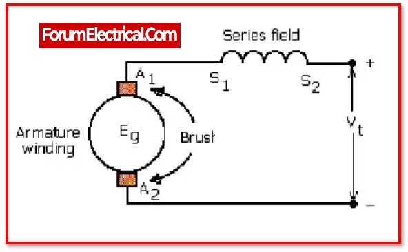
(a) Series wound DC Generator
Series wound DC generator which has the field winding connected in series with the armature winding.
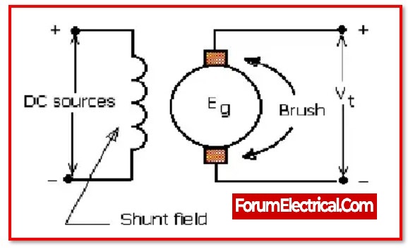
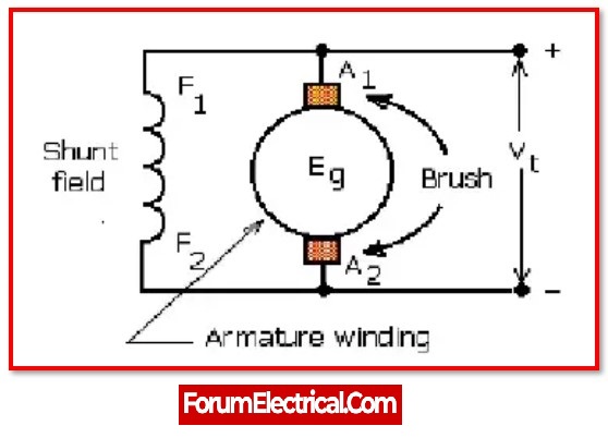
(b) Shunt wound DC Generator
Shunt wound DC generator which has the field winding running in parallel with the armature winding.
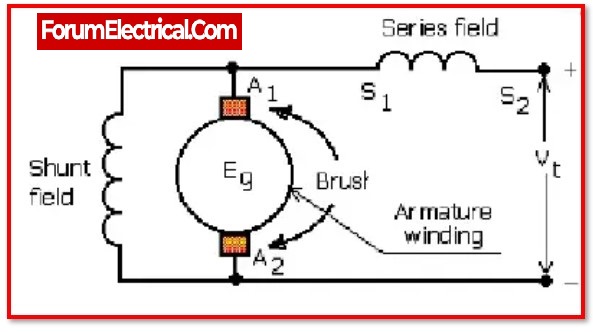
(c) Compound wound DC Generator
Compound wound DC generator which is a combination of shunt winding and series winding.
Advantages of DC Generator
- DC generators generate significant output.
- These generators have a significant amount of load at their terminals.
- The construction of dc generators is a simple and basic process.
- They are used to provide an unequal distribution of output power.
- They are highly consistent with efficiency scores ranging from 85 to 95%.
- They provide a consistent output level.
- They are not only small but also quite light in weight.
Disadvantagesof DC Generator
- A transformer is incompatible with the operation of a DC generator.
- This generator suffers from a number of inefficiencies, including copper losses, mechanical losses, eddy current losses, and so on.
- A voltage drop may occur across long distances
- Since it has a split ring commutator, it will make the design of the machine more difficult.
- Expensive
- Requiring a lot of maintenance
- Sparks will be produced when the energy is being created, and a greater amount of energy will be lost during transmission.
Applications of DC Generator
- Separately excited type DC generators are utilised for both boosting and electroplating. A field regulator is used to provide electricity and lights.
- Using the regulator, the self-excited DC generator (or) shunt DC generator is utilised for electricity as well as regular illumination. It is suitable for battery illumination.
- The series DC generator is employed in lighting arc lights, as a steady current generator, and as a booster.
- A compound DC generator is used to deliver power to DC welding equipment.
- A level compound DC generator is used to give electricity to hostels, hotels, and workplaces, among other places.
- A DC generator is used to compensate for voltage drops inside Feeders.
Difference between AC Generator and DC Generator
| S.NO | AC GENERATOR | DC GENERATOR |
|---|---|---|
| 1 | A mechanical device that converts mechanical energy into alternating current (AC). | A mechanical device used to convert DC mechanical energy to DC electrical energy. |
| 2 | The structure of this generator is simple. | Because of slip rings and commutators, the structure of this generator has a complicated design. |
| 3 | The direction of current flow in this generator will reverse on a regular basis. | The current will flow in only one direction in this generator. |
| 4 | These generators are categorised as single-phase, three-phase, synchronous, and induction generators. | These generators are classified into two types: separately stimulated and self-excited. |
| 5 | This generator has a high voltage output while it is operating. | The voltage that is generated by this generator is rather low. |
| 6 | It does not possess any commutators. | It is equipped with commutators that direct the flow of electricity in a one direction. |
| 7 | This generator has a significant cost. | This generator has a modest cost. |
| 8 | Since slip rings have an unbroken (uninterrupted) and smooth surface, they are very efficient. | They are inefficient. Because, both the commutators & the brushes are readily exhausted. |
| 9 | Since the brushes are so efficient, the likelihood of a short circuit is relatively low. | Since the commutators & brushes wear out fast, the danger of a short circuit exists. |
| 10 | The armature serves as the rotor in this sort of generator at all times. | The armature in this sort of generator is either stator or rotor. |
| 11 | This generator requires less maintenance than others. | It requires routine maintenance. |
| 12 | This generator’s output would be easily distributed (supply distribution) through transformer. | This generator’s output is difficult to distribute due to the absence of a transformer. |
| 13 | In this generator, current may be induced in the stator/rotor. | In this generator, current may be induced in the rotor. |
| 14 | This generator is mostly used to provide power to micro motors and household electrical equipment such as mixers and vacuum cleaners. | This generator is primarily used to power big electric motors, such as those used in subway systems. |
The primary benefits of DC generators are their simple construction and design, parallel operation, and less system stability issues compared to alternators.
