
- Types of Generator Faults
- Internal Fault Types in a Generator
- External Fault Types in a Generator
- Devices for Generator Protection
- Protection from Insulation Failure
- Protection for the Stator Earth Fault
- Protection for a Rotor Earth Fault
- Protection against Unbalanced Stator Loading
- Protection from Stator Overheating
- Low Vacuum Protection
- Protection from the failure of the Lubricating Oil
- Protection from Boiler Firing Loss
- Protection from the failure of the Prime Mover
- Over Speed Protection
- Protection from Rotor Distortion
- Protection against the expansion difference between Rotating & Stationary Parts
- Protection from Vibration
- Backup Generator Protection
A generator experiences electrical stress on its
- Insulation,
- Mechanical forces on its parts, and
- Temperature rise.
These are the main reasons generator or alternator protection is required. A properly maintained machine in beneficial running condition maintains its stipulated rated performance for numerous years and can tolerate overload.
To ensure machine safety, overloads and abnormalities must be prevented. Even with efficient design, construction, operation, and preventive measures, machines can still malfunction. Generator protection devices reduce faults quickly.
An electrical generator might have internal or external faults. Generators are usually connected to an electrical system, so any failure in the power system should be cleared from the generator immediately to avoid irreparable damage.
Generator faults are numerous and varied. This is why generators and alternators have many protections. Generator protection is discriminative and non-discriminative. Coordination of systems and settings is essential to achieving a sensitive, selective, & discriminative generator protection mechanism.
Types of Generator Faults
- Internal Faults and
- External Faults
are the most common types of generator faults.
Internal faults are caused by difficulties within the generator components, while external faults are caused by abnormal operating conditions & malfunctions on external networks.
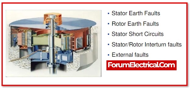
Internal Fault Types in a Generator
Internal faults might be electrical or mechanical in design.
1). Stator Faults
- Overheating of windings: Overheating of the stator windings can be generated by persistent overloads
- Fault in the windings from phase to phase: Phase-to-phase & earth faults are induced by insulation failure.
- Phase-to-earth defect in windings: Phase-to-earth faults are induced by insulation failure.
- Inter-turn fault
2). Faults in the Rotor
- Fault in the earth
- Short-circuit winding (wound rotor)
- Rotor overheating is caused by imbalanced currents at stator, which can occur as a result of:
- Trip with a single pole
- Faulty stator winding
- Sequence of negative phases
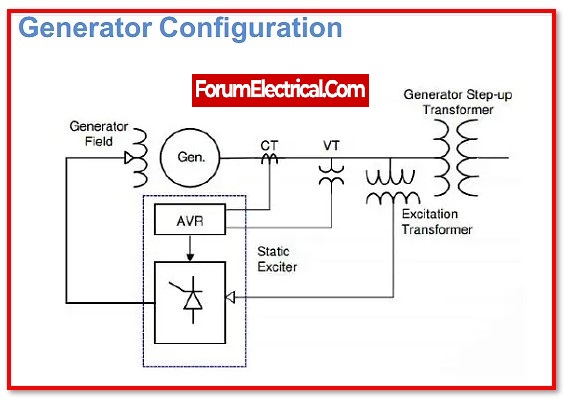
3). Loss of Field / Excitation (An AC generator’s field is made up of coils of conductors that obtain a voltage from an electrical source (also referred to excitation) & generate a magnetic flux.
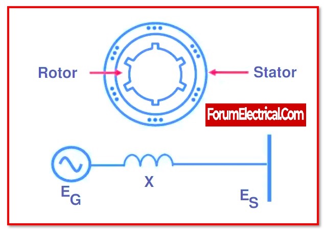
4). Out-of-Step Generator
5). Motor Function
6). Overheating bearings and a lack of lubrication oil pressure
7). Vibration

External Fault Types in a Generator
Faults in the external power system & abnormal operating conditions include:
1). External short-circuiting
2). Generator connection that is not synchronized – An external short-circuit, the switching off of an essential inductive load, or a defect in the excitation system can all cause synchronism to be disrupted.
3). Out of step (pole slippage or synchronization loss) -A network system problem that is uncleared or slow to clear might cause generators to slip poles or become “out-of-step” with the other components of the system.Mechanical stresses on the shaft and substantial power swings interrupt power system voltages.
4). Overloads – Overspeed is caused by an immediate shutdown of the complete load or a significant drop in load.
5). Overspeed
6). Unbalanced phase sequence & negative phase sequence
7). Over and under frequency
8). Under-voltages & over-voltages
Devices for Generator Protection
The most expensive components of power systems are generators. The subsequent devices are used to safeguard AC & DC generators from inherent faults.
Two categories can be utilized for categorizing the many different generator protection measures:
- Protective relays to identify faults outside the generator and
- Protective relays to identify faults inside the generator.
There are protection relays directly connected to the
- Generator and transformer,
- Lightning arrestors,
- Over speed guards,
- Oil flow and temperature measurement devices
for shaft bearing, stator winding, transformer winding, and transformer oil.
Some of these preventive arrangements simply alarm during irregularities and do not trip.
The other protective methods operate the generator’s master tripping relay. It should be remembered that no protective relay can avoid a fault, only indicate and decrease its length to prevent high generator temperature rise and permanent damage.
To mitigate the impacts of lightning & other voltage surges on the generator, surge capacitors or diverters are usually installed. Typical generator protection techniques are briefly covered below:
1). Protection from Insulation Failure
2). Protection for the Stator Earth Fault
3). Protection for a Rotor Earth Fault
4). Protection against Unbalanced Stator Loading
5). Protection from Stator Overheating
6). Low Vacuum Protection
7). Protection from the failure of the Lubricating Oil
8). Protection from Boiler Firing Loss
9). Protection from the failure of the Prime Mover
10). Over Speed Protection
11). Protection from Rotor Distortion
12). Protection against the expansion difference between Rotating & Stationary Parts
13). Protection from Vibration
14). Backup Generator Protection
Protection from Insulation Failure
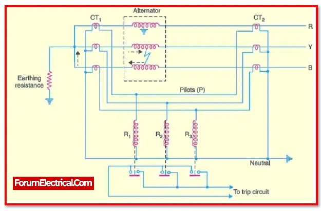
The longitudinal differential protection of the generator serves as the primary defence against phase-to-phase (or) phase-to-earth fault in the stator winding. Inter-turn fault protection is the second-most important safety method for stator windings.
In past experiences this type of protection wasn’t thought to be necessary because a break in the insulation between two points in the same phase winding that are in the same slot and have a different potential quickly turns into an earth fault, which is then picked up by either the stator differential protection (or) the stator earth fault protection.
A generator is made to have a relatively high voltage compared to its output, so it has a lot of wires in each slot. With the size & voltage of generators getting larger, this type of protection has become an essential for each of the large generators.
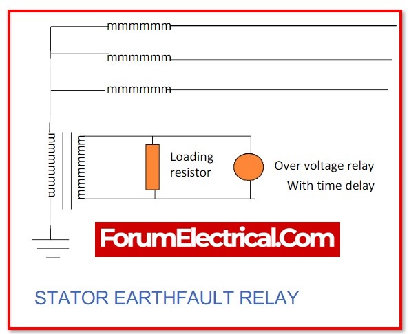
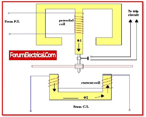
Protection for the Stator Earth Fault
When the neutral of the stator is connected to earth through a resistor, a CT-current transformer is installed in the connection between the neutral and earth. When the generator is connected up straight to the bus bar, an inverter time relay is connected across the CT secondary. For the same reason, an instantaneous switch is used when a generator sends power through a delta-star transformer.
In the first condition, the earth faults relay must be rated with the systems other fault relays. In this condition, inverted time relay is employed.
In the second condition, however, the earth fault loop is limited to the stator winding & the primary winding of the transformer.
Since there are no other earth fault relays in system, there is no requirement to grade or separate them. Instantaneous Relay is better in this condition.
Protection for a Rotor Earth Fault
If there is only one earth fault, it doesn’t cause any major problems with the generator. However, if there is a second earth fault, part of the field winding will short-circuit, causing an unbalanced magnetic field in system.
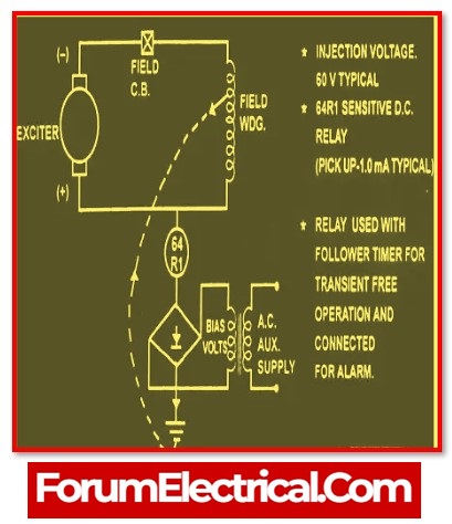
This can cause major mechanical damage to the generator’s bearings. There are three ways to find out what type of problem is in the rotor. These are the steps:
1). Potentiometer method
2). AC injection method
3). DC injection method
Protection against Unbalanced Stator Loading
In the stator circuit, unbalanced loading results in negative sequence currents. The negative sequence current induces a double-frequency current in rotor by causing a reaction field to rotate at twice the rotor’s synchronous speed. This too high current overheats the rotor circuit, particularly in the alternator.
The differential protection built into the generator would instantly correct any unbalancing that resulted from a malfunction in stator winding itself. Depending on the way the system’s protection is coordinated, an unbalance that results from an external malfunction or an unbalanced load may go undetected or continue for a long time. Installing a negative phase sequence relay with characteristics compatible with the machine’s withstand curve will then fix these errors.
Protection from Stator Overheating
The generator’s stator winding can overheat as a result of overload. The stator winding can overheat for a number of reasons, including
- Overloading,
- Cooling system failure, &
- Insulation failure of the stator laminations.
Temperature sensors implanted in stator winding are used to identify the overheating at various locations. The resistance components that make up the temperature detector coils typically make up one arm of the Wheatstone bridge circuit.
Smaller generators, typically those under 30 MW, lack inbuilt temperature coils but are instead typically equipped with thermal relays, which are set up to monitor the current flowing through the stator winding.
This setup only detects overheating brought on by overloading; it offers no Défense against overheating carried on by faulty cooling systems or shorted stator laminations.
Although devices for monitoring continuous flow,
- Negative phase sequence relays, &
- Over current relays
are also employed to some extent to provide thermal overload protection.
Low Vacuum Protection
This protection, which is often installed on generating sets larger than 30 MW, compares the vacuum with atmospheric pressure using a regulator. The secondary governor is used by the regulator to unload the set-in current practice till normal vacuum conditions are again present. The primary circuit breaker trips and the stop valves are closed if vacuum conditions do not improve to below 21 inches.
Protection from the failure of the Lubricating Oil
Since the lubricating oil is typically obtained from the exact same pump as the governor oil and since a failure of the governor oil will cause the stop valve to automatically close, this protection isn’t considered to be needed.
Protection from Boiler Firing Loss
There are two ways to find the loss of boiler firing.
In the first method, the fan motors have normally opened (NO) contacts that can trip the generator if more than the two motors fail.
The second method makes use of boiler pressure contacts that, if the boiler pressure drops below about 90%, unload the generator.
Protection from the failure of the Prime Mover
The generator will continue to operate in motoring mode, which means it draws electrical energy from the electrical system rather than delivering it to the system, if the prime mover is unable to provide mechanical energy to the generator.
In a steam turbine, the steam serves as a coolant to keep the temperature of the turbine blades constant. Due to frictional warming brought on by a supply failure, turbine blade distortion will develop.
In addition to placing a significant driving strain on the generator, the loss of steam supply can seriously harm mechanical components. For this, a reverse power relay is employed. The reverse power relay will be triggered by the generator set at the point the generator starts to rotate in driving mode.
Over Speed Protection
While mechanical over speed mechanisms on steam and hydro turbines that work directly on steam throttle valve (or) main step valve are typical, it is uncommon to back these devices up with an over speed relay on steam-driven sets.
On hydroelectric units, however, it is regarded as best practice because the governor responds almost slowly and the set is more likely to overspeed. When installed, the relay is often powered by the permanent magnet generator that also controls the governor.
Protection from Rotor Distortion
The top & bottom of the turbine casing cool at different rates after shutdown, and this unequal temperature distribution tends to ruin the rotor. It is common to rotate the rotor slowly through the cooling down time in order to reduce disruption.
The fitting of shaft eccentricity detectors is now considered normal procedure due to the stresses involved with large contemporary rotors.
Protection against the expansion difference between Rotating & Stationary Parts
Due to the differences in mass, the rotor heats up at a different pace than the case during the running up phase. As a result, the rotor and case expand at different rates, and this uneven expansion must be overcome.
In order to accomplish this, it is suggested that certain joints on casing of the bigger machine receive independent supply of steam.
In order to help the operator feed the steam to the proper places and to alert them to any potentially harmful expansion, it is desirable to provide a method to measure the axial expansion.
The shaft axial expansion detector is essentially the same as the rotor distortion detector, with the exception that the detector magnets are permanently attached to the turbine casing.
Protection from Vibration
The bearing pedestals are often where vibration detectors are installed. The detector comprises of two permanent magnets in the shape of a U and a coil set on springs.
The coil’s voltage output, which is inversely proportionate to the intensity of the vibration, is then routed through integrating circuits and into an interval-indicating instrument.
Backup Generator Protection
Always provide backup protection while using a machine with a high rating, such as an alternator or synchronous generator.
Backup protection relays must be activated to clear faults if the proper protection scheme was not able to fix them. For this, over current relays are typically employed.
Modern machines frequently have synchronous reactance more than 100%, hence the sustained fault current delivered from the machinery into an external fault is always lower than the typical full load current.
Because their current settings need to be closer to full load and their time sitting must be short in order to achieve operation, ordinary IDMT relays would not perform properly and would likely lack discriminating ability with respect to the other system’s over-current relays. This is because their time sitting must be short.
Furthermore, the machine would likely lose field and the over-current relay could probably activate, disconnecting it too quickly. It has become common practice to use an over-current relay along with an under-voltage relay, with the latter relay governing the fault settings of the former, in order to solve the issue.

