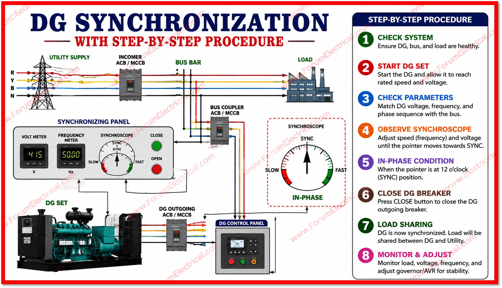
Diesel Generator (DG) synchronization is the controlled process of connecting a diesel-driven alternator to a live electrical bus, another running generator, or the utility grid so that power flows smoothly without electrical shock to the machine, the switchgear, or the connected load.
- Why is Synchronization Necessary?
- Four Synchronizing Conditions
- Methods of Synchronization
- a). Manual Synchronization
- b). Automatic Synchronization
- Typical Synchronizing Panel Components
- Step-by-Step Synchronizing Procedure
- Protection and Interlocks
- Common Faults during Synchronization
- Applications
- Conclusion
Because an alternator is a rotating source of alternating voltage, closing its breaker onto an already-energized system while its own output does not match that system is equivalent to slamming two out-of-step magnetic fields together.
The result can be a violent inrush of current, torque shock on the shaft and coupling, breaker damage, and even loss of synchronism severe enough to trip protection relays across the plant.
Proper synchronization eliminates this risk and is therefore a core competency for anyone commissioning, operating, or maintaining standby, prime, or parallel-generation diesel plants.
Why is Synchronization Necessary?
Most industrial and commercial sites rarely run on a single generator. Data centers, hospitals, manufacturing plants, marine vessels, and utility substations commonly operate two or more DG sets in parallel, or a DG set in parallel with grid supply, to achieve higher capacity, built-in redundancy, and the ability to perform maintenance on one machine while others carry the load.
Synchronization is the technical gatekeeper that makes safe parallel operation possible.
Four Synchronizing Conditions
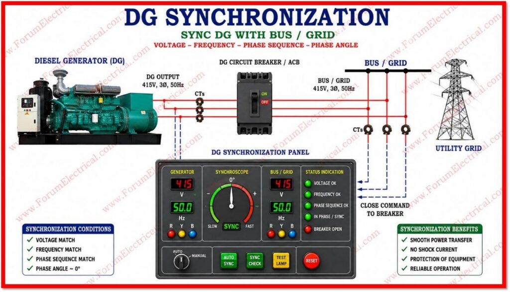
Before a generator breaker is allowed to close, four electrical quantities of the incoming machine must be matched, within tolerance, to the running bus:
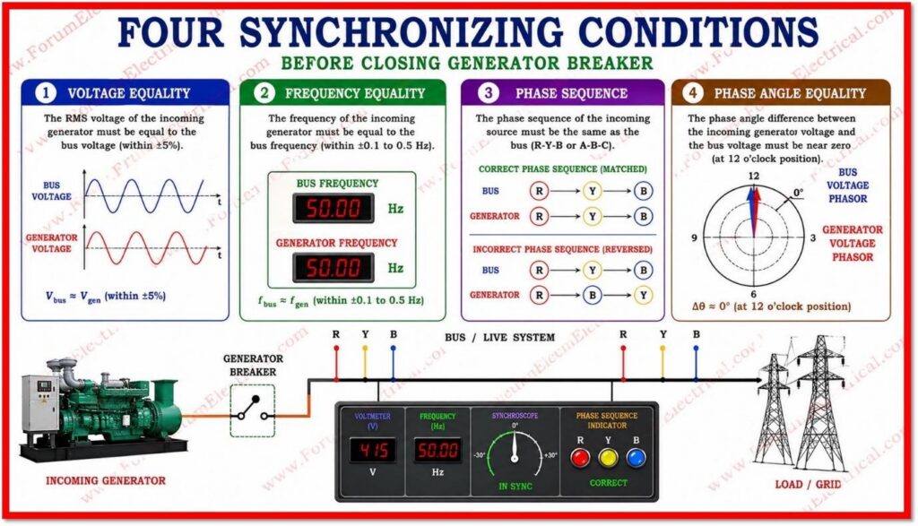
- Voltage Equality: the RMS magnitude of the incoming generator’s voltage must equal the bus voltage, typically within about 5 percent, otherwise a sudden reactive-power surge occurs at closure.
- Frequency Equality: the incoming machine’s frequency must closely track the bus frequency, generally within 0.1 to 0.5 Hz, so the two sources rotate at effectively the same electrical speed.
- Phase Sequence: the phase rotation (R-Y-B or A-B-C) of the incoming source must match the bus exactly; a reversed sequence, even with matching voltage and frequency, will cause a violent short-circuit-like event on closure.
- Phase Angle: the instantaneous voltage waveforms of the incoming source and the bus must be in phase, ideally within about 10 to 15 electrical degrees, at the moment the breaker closes.
Methods of Synchronization
a). Manual Synchronization
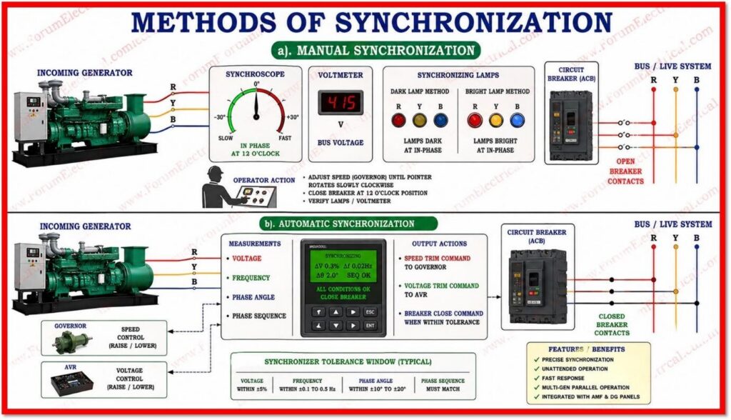
In manual synchronization, an operator watches a synchroscope, a dial-type instrument whose pointer rotates clockwise when the incoming generator runs slightly faster than the bus and counter-clockwise when it runs slower.
The operator fine-tunes the governor speed reference until the pointer rotates slowly clockwise and closes the breaker as the pointer approaches the twelve o’clock position, which represents zero phase difference.
A voltmeter and a set of synchronizing lamps, connected across the open breaker contacts, provide a secondary visual check: in the classic dark-lamp method the lamps dim to black at the in-phase instant, while in the bright-lamp method they flare brightest at that same instant.
b). Automatic Synchronization
An Automatic Synchronizer Unit (ASU) performs the same task electronically.
It continuously measures the voltage, frequency, and phase angle difference between the incoming generator and the bus, sends raise or lower pulses to the engine governor to trim speed, sends raise or lower pulses to the Automatic Voltage Regulator (AVR) to trim voltage, and issues a breaker-close command only when all four conditions fall within pre-set tolerance windows, usually with a small closing lead-time compensation to allow for breaker closing delay.
Modern DG control panels and Automatic Mains Failure (AMF) panels integrate this function as standard, enabling unattended parallel operation and load sharing between multiple sets.
Typical Synchronizing Panel Components
| Component | Function |
| Synchroscope | Indicates phase and slip relationship between incoming set and bus |
| Dual Voltmeter | Compares incoming and bus voltage magnitudes |
| Dual Frequency Meter | Compares incoming and bus frequency |
| Synchronizing Relay (25) | Automatically permits breaker closing only within set tolerances |
| Governor & AVR Trim Controls | Adjust engine speed and excitation to align frequency and voltage |
| Circuit Breaker | Physically connects the generator to the bus on command |
Step-by-Step Synchronizing Procedure
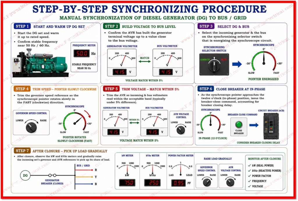
- Step 1: Start the DG set and warm it up to rated speed, confirming stable frequency near 50 Hz or 60 Hz as applicable.
- Step 2: Confirm the AVR has built the generator terminal voltage up to a value close to the bus (or) grid voltage.
- Step 3: Select the incoming generator & the bus on the synchronizing selector switch that is energizing the synchroscope circuit.
- Step 4: Trim the governor speed reference so the synchroscope pointer that used to rotate slowly in the fast (clockwise) direction.
- Step 5: Trim the AVR so incoming & bus voltmeters that read within the acceptable band which is typically under 5% difference.
- Step 6: As the synchroscope pointer approaches the twelve o’clock, in-phase position, issue the breaker-close command, accounting for the breaker’s own closing delay.
Protection and Interlocks
Because a failed or mistimed synchronization can be destructive, synchronizing panels are backed by dedicated protection.
A synchronizing check relay (device number 25) blocks the close command unless voltage, frequency, and phase-angle differences are simultaneously within tolerance. Reverse power relays (32) detect a generator that has become a motor, drawing power instead of supplying it, which typically indicates a governor or fuel problem after paralleling.
Over/under-frequency and over/under-voltage relays trip the machine if it drifts outside safe operating limits.
Breaker close-coil supervision and anti-pump relays prevent repeated futile closing attempts.
Many modern panels also include a check-synchronizing relay as a hardware-independent backup to the electronic auto-synchronizer, so that even a software fault cannot force an out-of-phase closure.
Common Faults during Synchronization
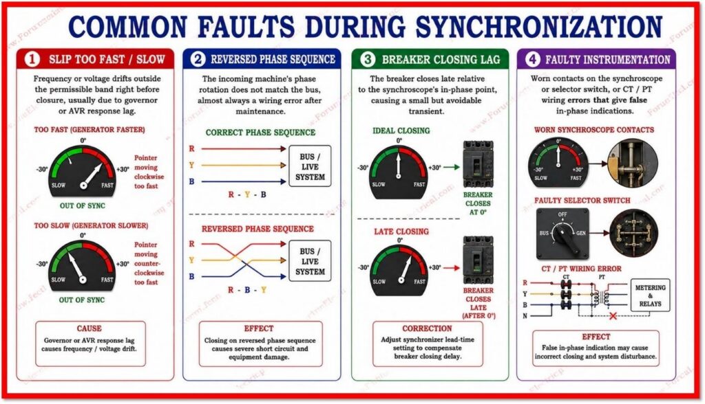
- Slip too fast/slow: frequency or voltage drifts outside the permissible band right before closure, usually due to governor or AVR response lag.
- Reversed phase sequence: the incoming machine’s phase rotation does not match the bus, almost always a wiring error after maintenance; this must be corrected before any attempt to close.
- Breaker closing lag: the breaker closes late relative to the synchroscope’s in-phase point, causing a small but avoidable transient; corrected by adjusting the synchronizer’s lead-time setting.
- Faulty instrumentation: worn contacts on the synchroscope or selector switch, or CT/PT wiring errors that give false in-phase indications.
Applications
DG synchronization is used wherever generation sets must combine capacity or hand over load seamlessly:
- Hospitals and data centers running N+1 diesel backup,
- Industrial captive power plants paralleling with the utility grid for peak shaving,
- Marine vessels paralleling multiple ship generators and
- Telecom or oil-and-gas sites running islanded microgrids of several diesel sets sharing load in proportion to their rating.
Conclusion
DG synchronization is not a peripheral switching task but a safety-critical discipline that protects rotating machinery, switchgear, and connected loads from the severe electrical and mechanical stresses of an out-of-step connection.
If performed manually with a synchroscope and lamps or automatically through a microprocessor-based synchronizer, the underlying requirement never changes: matched voltage, matched frequency, correct phase sequence, and a near-zero phase angle at the instant of breaker closure.
The primary function of this procedure, backed by properly configured protection relays, is what allows modern facilities to run diesel generators in parallel with confidence, flexibility, and minimal risk of downtime.

