
- What is Time Constant?
- Transient response of RC and RL Circuit
- Charge and Discharge Cycle of RC Circuit
- High-Capacitive Discharge Current
- Time Constant (τ) of an RC Circuit
- RC Integrator
- RC Differentiator
- Time Constant (τ) of an RL Circuit
- High Voltage generated in RL Circuit
- Time Constant (τ) of an RLC Circuit
- Universal time Constant – τ Formula
- How to find time constant with resistance and inductance?
What is Time Constant?
In physics and engineering, the time constant – generally symbolised by the Greek letter τ (tau) – is used to quantify the response to a step input of the first-order, linear time-invariant (LTI) control system. A first-order LTI system’s key characteristic unit is the time constant.
The time constant is widely used to define an RLC circuit’s response.
Let continue by determining the time time constant for an RC circuit & the time constant for an RL circuit.
Transient response of RC and RL Circuit
- Capacitors resist voltage fluctuations. Changes in current are opposed by inductors.
- In a capacitor circuit, the time constant is the product of the resistance (R) & capacitance (C) . T = RC. An inductor circuit’s time constant is equal to the inductance (L) divided by the resistance (R) . T = L/R.
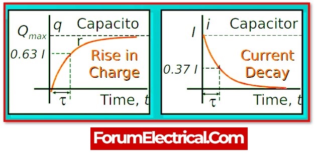
- A time constant is the amount of time required to alter the voltage (V) across a capacitor (or) the current (I) flowing through an inductor by 63.2%.
- Transient responses in series RC & RL circuits may be examined using time constants.
- A transient response is a situation that occurs only until a steady-state value of either voltage (or) current is attained.
- Transient responses are related with non-sinusoidal voltage & current waveforms (such as square, rectangular, and triangular) as well as the on and off of a DC source.
- Inductance and capacitance have the effect of changing the shape of non-sinusoidal waveforms.
- Filtering, wave-shaping, & timing are provided by RC and RL circuits.
- The capacitor is the most frequent kind of device. Capacitors are less expensive and smaller than inductors, and they do not have significant magnetic fields.
Charge and Discharge Cycle of RC Circuit
1). Charge Cycle of RC Circuit
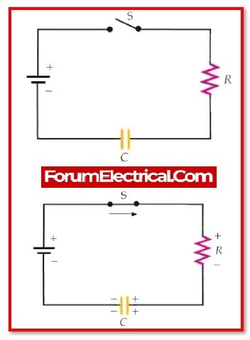
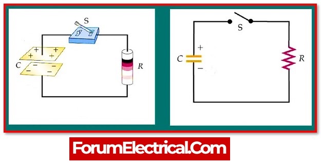
- An RC series circuit consists of a voltage source connected in series with a resistor & a capacitor. The charge (or) discharge is provided via a switch.
- The time t0 represents the first time the switch is closed. t1 is the time at which the capacitor is fully charged or discharged. Five time constants are used to calculate the time required to completely charge (or) discharge the capacitor.
- The source voltage immediately climbs from zero to maximum & remains there.
- When the capacitor charges, the circuit current rapidly increases to its maximum & then gradually drops. When the capacitor is completely charged, the current is zero and stays that way.
- The voltage across the resistor rapidly increases to its maximum and then gradually decreases.
- The voltage across the capacitor steadily rises to its maximum value.
2). Discharge Cycle of RC Circuit
- When the switch is shifted to the discharge position, the source voltage decreases to zero instantaneously.
- The discharge current rapidly increases and then gradually declines. The resistor voltage immediately reaches its maximum.
- The voltage progressively lowers until it reaches zero.
- The capacitor voltage progressively lowers until it hits zero.
High-Capacitive Discharge Current
The circuit may be configured up to deliver a high discharge current for an instant (in seconds) of time. This is often used in flash photography.
Time Constant (τ) of an RC Circuit
The time needed to charge or discharge a capacitor to 63.2% or 36.8% of its maximum voltage is a time constant.
T = RC
τ = RC = 1/2πfC
where,
R is in ohms,
C is in Farads,
τ = Time constant (seconds),
fC = cut-off frequency (hertz).
The voltage is 99.3% after five time constants, which is regarded completely charged.
RC Integrator
A circuit that provides an approximation of the mathematical process of integration is known as an RC integrator.
A simple integrator may under some circumstances, generate an output that is a running sum (add) of the input, which is consistent with the fact that integration is a summing operation.
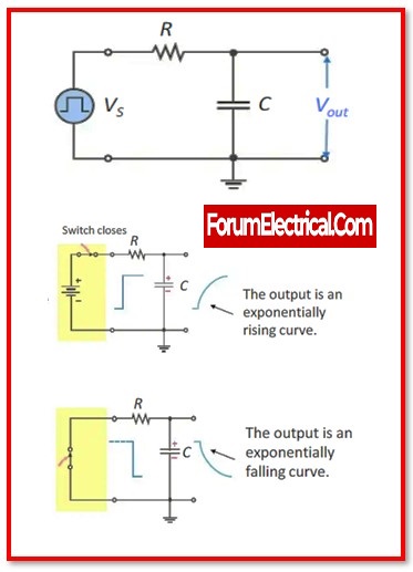
In response to the pulses, the capacitor will charge & discharge when a pulse generator is linked to the input of an RC integrator.
As the pulse generator’s power supply runs low, the relatively low internal impedance of the generator makes it seem as if a closed switch has been installed in lieu of the battery.
RC Differentiator
A circuit that provides an approximation of the mathematical process of differentiation is referred to as an RC differentiator.
A simple differentiator may provide an output that is the rate of change of the input under certain circumstances& differentiation is a process that determines the rate of change.
When a pulse generator is connected (linked) to the input of an RC differentiator, the capacitor acts as an instantaneous short to the rising edge and sends it on to the resistor.
This causes the pulse generator to be differentiated.
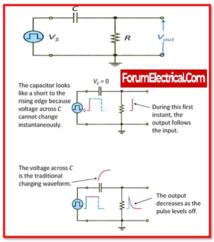
When the first edge has passed, the capacitor will start to charge, and the output voltage will start to fall in an exponential manner.
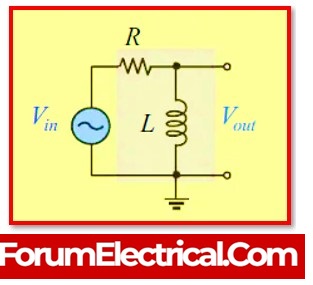
Time Constant (τ) of an RL Circuit
Inductor with inductance -“L” in series with resistance -“R,” whose time constant “” in seconds is given by:
τ = L/R
Where,
R – Resistance in series,
L – Inductance of the Inductor.
High Voltage generated in RL Circuit
When an RL circuit is opened, a high voltage is produced.
When the circuit is opened, an inductor’s magnetic field collapses. A strong voltage will be produced by the collapsing magnetic field.
To prevent this high voltage from damaging circuit components, diodes are often utilised in inductor circuits like as relays.
Time Constant (τ) of an RLC Circuit
The RL and RC time constants are mixed in an RLC circuit, makes determining the time constant difficult. So, compute that which known as the Q-Factor (quality factor).
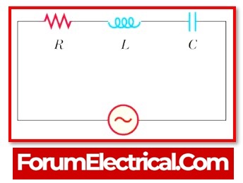
1). Time Constant (τ) of Series RLC Circuit
Q-Factor = 1/R √ (L/C)
2). Time Constant (τ) of Parallel RLC Circuit
Q-Factor = R √ (C/L)
Where,
R – Resistance in series,
L – Inductance of the Inductor and
C – Capacitance of the capacitor.
Universal time Constant – τ Formula
Change = Final Value– Start Value(1 – 1/et/τ)
Where,
Final – Value(Ultimate value) of the calculated variable after infinite time,
Start – Initial value of the calculated variable,
e – Euler’s number (i.e., ≈2.7182818),
t – Time in seconds and
τ – Time constant for circuits (seconds).
The usage of RC circuits is considerably more common than the use of RL circuits.
How to find time constant with resistance and inductance?
For a circuit consisting of a resistor and an inductor, the time constant may be determined by taking the quotient (division) of the inductance measured in henrys and the resistance measured in ohms,
τ=L/R
The value (measurement) of the time constant is directly proportional to the value of the inductance, whereas the value of the resistance is inversely proportional to the value of the inductance.
