
- Why are Pre-Commissioning Tests Performed?
- What are the Tests before Commissioning a Transformer?
- Importance of On-Site Transformer Testing
- What are the four basic types of transformer tests?
- Pre-Commissioning Test Types
- Preparing for Transformer Pre-Commissioning Tests
- Tools and Equipment
- Pre-Commissioning Tests Procedure
- Step-1: Preliminary Checks
- Step-2: Routine Testing
- Step-3: Performing Type & Special Tests
- Step-4: Recognizing & Analyzing Outcomes
- Common Pre-Commissioning Test Challenges and Troubleshooting
- What is the difference between Testing and Commissioning?
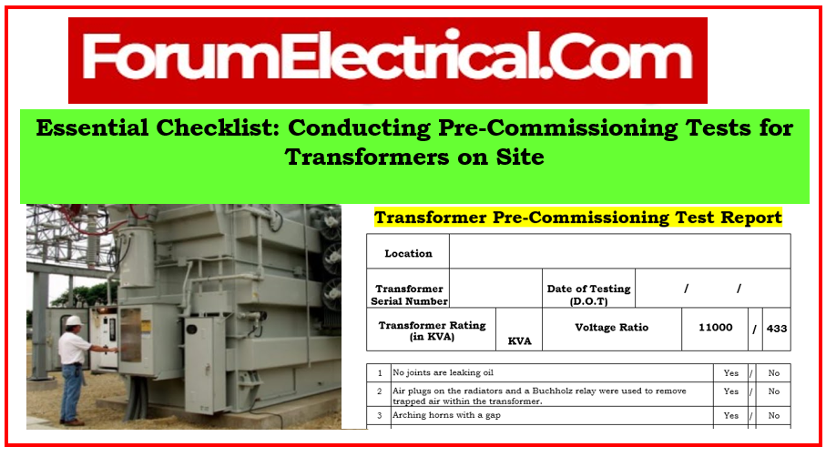
- Checklist
Transformers function as essential equipment in power systems, allowing electrical energy to be transmitted and distributed.
An essential phase in the installation process, the Pre-Commissioning Test of Transformers includes a series of testing and evaluations aimed at providing the transformer’s reliability, functionality, and safety before it becomes operational.
Pre-commissioning tests are a complete set of tests performed on transformers prior to their commissioning for active operation.
These tests are important quality control measures that ensure the transformer fulfills mentioned requirements, performs within safe limits, & operates as expected in the planned electrical system.

Why are Pre-Commissioning Tests Performed?
- Determining that the transformer is operationally ready and meets the performance standards.
- Prior to energization, identify any potential defects, damages, or variations from the intended outcome.
- Ensuring that industry standards, laws, and safety practices are followed in order to avoid potentially hazardous circumstances during operation.
- Enabling optimal functionality and efficiency by resolving issues before deployment in the electrical grid.
These tests are essential not only for the transformer’s immediate performance, additionally for its long-term reliability and safety as part of the wider electrical system.
Individuals and organizations can decrease the risks associated with the malfunctioning equipment, eliminate potential transformer damage, ensure efficient power transmission, & ultimately protect the entire electrical network by undertaking pre-commissioning tests.
What are the Tests before Commissioning a Transformer?
It is recommended to perform the following electrical testing before commissioning a transformer:
- Transformer Turn Ratio
- CT Bushing Ratio
- Power Factor/Dissipation Factor (50/60 Hz)
Importance of On-Site Transformer Testing
Conducting extensive pre-commissioning tests at the on-site is essential for several reasons:
Ensure Functionality and Dependability
Pre-commissioning tests evaluate transformer operation, ensuring they work within defined parameters prior to incorporation into the electrical grid.
On-site testing validates that the transformer can perform its intended responsibilities reliably, reducing the possibility of operational faults (or) breakdowns during the service.
Identifying Potential Problems Prior to Commissioning
These tests are used as a preventative measure, allowing for the identification and correction of potential faults or defects before the transformer is put into service.
Addressing issues in advance reduces downtime & potential damage to the transformer & associated systems after commissioning.
Industry Standards & Regulations Compliance
Pre-commissioning tests ensure that the transformer complies with manufacturer specifications, industry standards, & regulatory requirements.
Compliance with standards and regulations ensures a safe working environment, decreasing the risk of electrical hazards and assuring overall system safety for the personnel & equipment.
Some of the major standards followed in commissioning of power transformer are:
IEEE C57: IEEE standards in the C57 series cover a wide range of power transformer topics, including testing processes, specifications, and suggestions for specific transformer types.
IEEE 62: Specifies the procedures for performing diagnostic tests on transformers and other electrical equipment.
IEC 60076: IEC 60076 Series includes power transformer standards such as design, specifications, & testing techniques.
What are the four basic types of transformer tests?
Four Transformer Testing Methods
- Turns Ratio Testing
- Power Factor Testing
- Insulation Resistance Testing
- Resistance Testing
Pre-Commissioning Test Types
Pre-commissioning tests for the transformers at a location include an array of evaluations to certify the transformer’s readiness for service. These tests are classified into several types based on their different methodologies:
- Routine Test
- Type Test
- Special Test
The in-depth explanations for these tests can be found within the content titled Different Types of Transformer Testing.
Preparing for Transformer Pre-Commissioning Tests
Having the correct equipment and assuring site preparation are essential for transformer pre-commissioning testing. Here’s how it works:
Site Preparation
Checklist for Choosing an appropriate location:
- There should be enough room for the transformer & testing equipment.
- Simple installation and operation of devices.
- Proper ventilation is required to dissipate heat throughout testing.
- Adequate grounding is required to assure safety during testing.
- Temperature & humidity levels should be appropriate.
- Safety protocols include clearly delineated safety zones and the observance of safety regulations.
Precautions and Safety Measures
- Ensure that all personnel are wearing appropriate PPE (helmets, gloves, goggles, and so on).
- Conduct safety briefings to ensure every individual understands emergency procedures.
- Implement lockout/tagout procedures to avoid accidental energization.
- Install fire extinguishers and protocols.
- A first aid kit is provided, as are qualified workers.
Tools and Equipment
Instruments Required for Testing
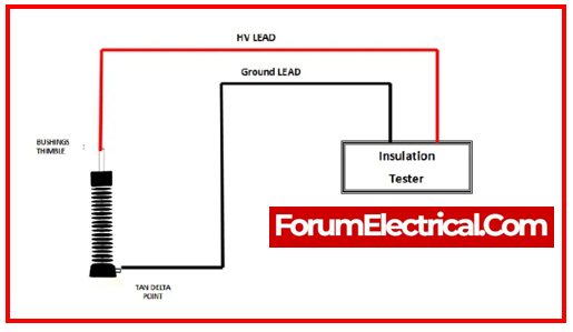
Insulation Resistance Tester: This device measures the resistance of insulation.
TTR Tester: Transformer Turns Ratio (TTR) Tester device calculates the turns ratio.
Power Factor Test Equipment: Dielectric loss is measured by Power Factor Test Equipment.
Winding Resistance Tester: This device measures the resistance in windings.
Voltage & Current Transformers: These are required for exact measurements.
Temperature Sensors: Check the temperature of the transformer.
Oil Testing Equipment: Used to determine the quality & dielectric strength of oil.
Calibration Tools: Instruments for calibrating and verifying the accuracy of the testing devices.
Safety Tools: Insulating gloves, mats, barriers, and other safety devices are useful when working with live equipment.
Calibration & Maintenance of Testing Equipment
Calibration on a Regular Basis: Follow the manufacturer’s guidelines for frequent calibration of testing equipment.
Maintenance Log Register: Maintain logs for each piece of equipment, recording maintenance, calibration, & any concerns.
Training: Educate employees on proper equipment usage, maintenance, & calibration processes.
Spare Components: Keep spare components on hand for quick replacement if necessary.
Storage & Handling: Store & handle equipment properly to avoid damage or degradation.
Pre-Commissioning Tests Procedure
Step-1: Preliminary Checks
Transformer Component Inspection
Visual inspection: Look for physical damage, leaks, or any irregularities in the transformer body, tap changers, bushings, & cooling system.
Oil Quality: Examine the oil level, color, and clarity; sample for laboratory examination if necessary.
Bushings and insulation: Check that the bushings and insulation are in good condition.
Tap Changers: Check the functionality and connections of the tap changers.
Wiring Inspection: Evaluate control, protection, & power wiring for adequate connections and insulation.
Step-2: Routine Testing
Step-by-Step Procedure for Each Test
Insulation Resistance Test: To test insulation resistance, apply a DC voltage between the windings and ground. Interpret the results to make sure they meet the requirements.
Winding Resistance Test: Determine resistance in the transformer windings & compare to manufacturer data.
Transformer Turns Ratio Test: Apply voltages to the primary and secondary windings to calculate the turns ratio. Check the design specifications.
Polarity Check: Confirm the correct polarity of the windings and connections.
Open Circuit and Short Circuit Test: Open and short circuit tests are performed to assess transformer properties such as core losses & impedance.
Result Interpretation
Compare the test results to manufacturer specifications & industry norms.
Step-3: Performing Type & Special Tests
Detailed Procedure for More Complex Tests
- To determine insulation quality, run tests that include power factor, capacitance, & dissipation factor based on following the standard IEC 60076-3.
- Measure partial discharges to evaluate insulation.
- High-voltage impulses are used to simulate lightning strikes & evaluate insulation strength.
- In heat run test, Supply rated current for an extended period of time to evaluate temperature rise & insulation performance under load based on following the standard IEC 60076-2.
Step-4: Recognizing & Analyzing Outcomes
Compare test findings to established standards (or) historical data.
Deviations (or) abnormalities may necessitate further research, modification, or corrective action.
Document and analyze results to ensure compliance with standards & operational needs.
Common Pre-Commissioning Test Challenges and Troubleshooting
Identifying Potential Issues
- Problems with Insulation: Unexpectedly low insulation resistance levels can indicate moisture or contamination.
- Winding resistance deviations may indicate damaged or malfunctioning windings.
- Incorrect connections can result in distorted test results or testing faults.
Troubleshooting and Correction Techniques
- To rule out errors, re-run the test to verify the findings.
- Isolate problematic sections and investigate for loose connections, physical damage (or) contamination.
- Refer to product documentation or contact specialists for assistance with unexpected readings or difficulties.
- Address detected issues as soon as possible by repairs, replacements (or) adjustments in accordance with customary processes.
What is the difference between Testing and Commissioning?
| Testing | Commissioning |
| Various tests known as static testing will be performed during service installation. This testing is typically performed to demonstrate the installation’s quality and workmanship. | After static testing is completed, dynamic testing gets started, which is known as “commissioning.” Commissioning is done to ensure that the systems work and meet their intended purpose & specifications. |
