
- Sources of Short Circuit Current
- Fundamentals of Short Circuit Analysis
- Different Methods of Short Circuit Calculation
- Reference Values of Short Circuit Calculation
- Different Short Circuit Fault
- How do you calculate Short Circuit Current?
- Why do we calculate Short Circuit Current?
- Applicable Standards
- Calculator
Sources of Short Circuit Current
In electrical power systems, short circuit current can arise from a variety of sources. Some of the most prevalent sources of short circuit current which are taken into account when design & protection calculations include:
- Utility Generation
- Local Generators
- Transformers
- Synchronous Motors
- Induction Motors
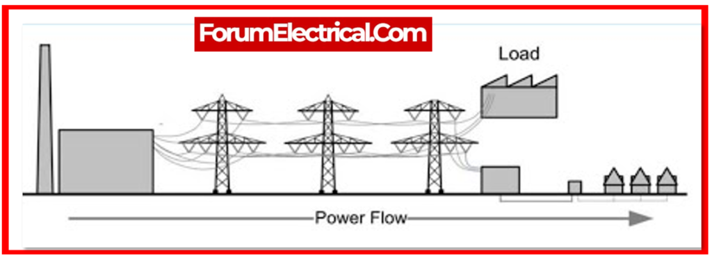
1). Utility Generation
Short circuit current might come from the utility power source as a result of power generation failures.
This might result in a high quantity of electricity flowing into the electrical power system, creating extensive damage to equipment & endangering personnel.
2). Local Generators
Local generation sources, which include diesel generators, can also produce short circuit current.
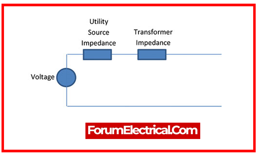
3). Transformers
Transformers are frequently mentioned as a cause of short circuit current. This is technically incorrect, because the transformer only distributes the short-circuit current created by generators (or) motors located ahead of it.
Transformers only impact the system voltage & current magnitude; they do not generate anything.
The short-circuit current produced by a transformer is dictated by its secondary voltage rating & reactance, the reactance of the generators and system to the transformer’s terminals, & the reactance of circuit from transformer to the short circuit.
4). Synchronous Motors
Synchronous motors are employed in a variety of industrial applications and can generate short circuit current under fault conditions.
Synchronous motors generate large amounts of short circuit current, making it difficult to defend against it.
5). Induction Motors
Induction motors are another typical source of short circuit current, & their performance during fault conditions varies depending on the type and location of the defect.
Induction motors provide moderate short circuit currents, which are easier for protection against than synchronous motors.
These sources of short circuit current may cause substantial damage to electrical equipment, endanger personnel, and result in protracted power outages.
- Fuses,
- Circuit breakers, and
- Relays
are used to safeguard equipment & personnel from the effects of a short circuit.
The proper selection and coordination of these protection devices is crucial to assuring the electrical power system’s safety and dependability.
Fundamentals of Short Circuit Analysis
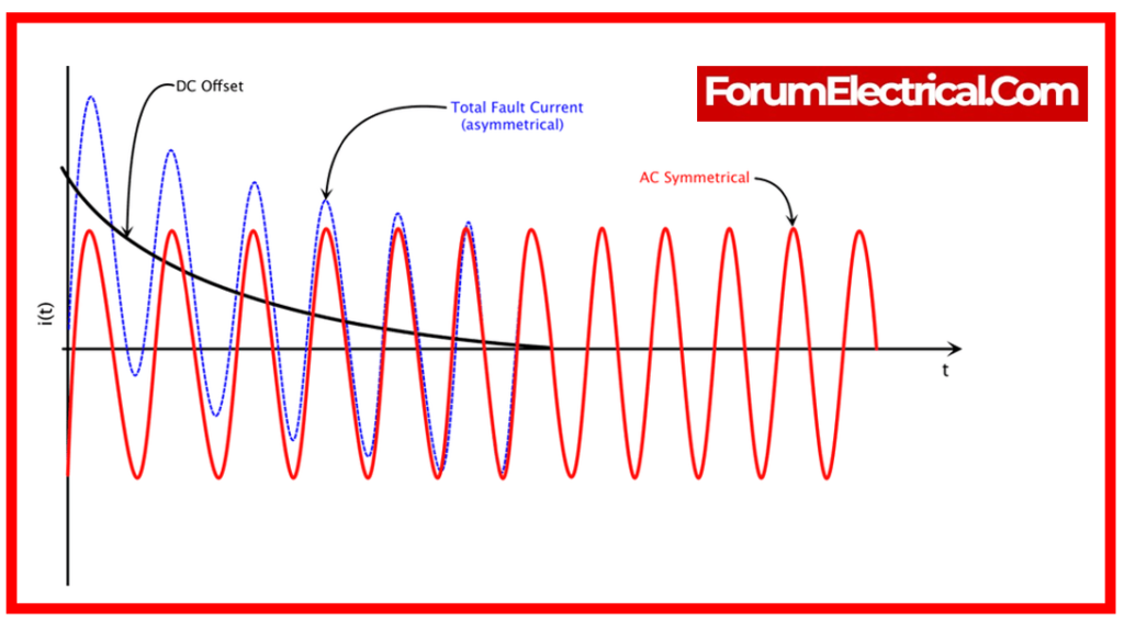
A short circuit current analysis determines the capacity of the short circuit current that the system has the ability of producing & compares it to the overcurrent protective device’s interrupting rating.
It is important to understand that the interrupting rating differs from the short circuit current rating (SCCR).
According to a basic electrical theorem, the short circuit current is determined by two key parameters:
- Total impedance from source to the fault point
- The system’s nominal voltage
The basic formula allows us to simply compute the short circuit current at fault location, & with those figures, we can examine the system, install protective devices, and prevent the facility from serious harm or damage.
IFault = V/Z
There are multiple methods for calculating short circuit currents.
Different Methods of Short Circuit Calculation
There are several ways for short circuit protection, including the
- Per-unit methods,
- Point-to-point methods, and
- Impedance methods.
Each method has unique qualities, advantages, and limits.
1). Per-Unit Method
QUALITY: The per-unit technique is widely used for short circuit protection. This method is based on describing the parameters of the system in per-unit values and normalizing them to a base value, which can be the system’s rated voltage or MVA. Short circuit calculations are then carried out utilizing these normalized values, & protective devices which include circuit breakers are chosen based on their per-unit ratings.
ADVANTAGES: The per-unit method is basic, effective, and makes it simple to coordinate protective devices. This is due to the fact that the per-unit values don’t depend on the absolute values of the system parameters.
2). Point-to-Point Method
QUALITY: The point-to-point method calculates the system’s impedance across the fault location & the source. The fault current is then estimated using Ohm’s Law, which divides the voltage at source by the system’s impedance. Protective devices are chosen based on their fault current and time-current characteristics.
ADVANTAGES: The point-to-point technique is more precise than the per-unit method because it takes into account the actual system parameter values.
DISADVANTAGES: However, it is more difficult and requires thorough system information.
3). Ohmic Method
QUALITY: The ohmic approach is another method for protecting against short circuits in the electrical power systems. This method involves estimating the impedance of the equipment being protected, including
ADVANTAGES: The impedance is then used to compute the maximum fault current that can pass via the equipment, & protective devices like fuses or circuit breakers are chosen based on this maximum fault current.
Reference Values of Short Circuit Calculation
The following are the reference values required for the calculation of the fault current.
Impedance Values for 3-Phase Transformers
| Rating | KV | KVA | Impedance Value |
| High Voltage (HV) Rating | 2.4 KV – 13.8 KV | 300 KVA – 500 KVA | Not less than 4.5% |
| High Voltage (HV) Rating | 2.4 KV – 13.8 KV | 750 KVA – 2500 KVA | 5.75% |
| General | < 600V | 15 KVA – 1000 KVA | 3% – 5.75% |
Reactance Values for Induction & Synchronous Machine
| Machine | Pole/Volt | Reactance Value |
| Salient Pole Generator | 12 Pole | 0.16 |
| 14 Pole | 0.21 | |
| Synchronous Motor | 6 Pole | 0.158 |
| 14 Pole | 0.20 | |
| Induction Motor | > 600 V | 0.17 |
| < 600 V | 0.25 |
Different Short Circuit Fault
1). Transformer Fault Current
Each transformer has the impedance value “%” stamped on the nameplate.
It is stamped because it represents a tested value obtained after a transformer has been produced.
The test goes as follows:
Step-1: A voltmeter is connected to the transformer’s primary, and the secondary 3-Phase windings are bolted together.
Step-2: An ampere meter is used to read the current flowing in the Three-Phase bolted fault on secondary.
Step-3: The voltage is gradually increased till the secondary full load current is detected on the ampere meter linked to the transformer secondary.
Example:
What does this indicate for a 1000 KVA 13.8KV – 480Y/277V system?
First, you must know the transformer’s full load amps.
Full Load Ampere = KVA/1.73 x L-LKV
FLA = 1000/1.732 x 0.48FLA = 1,202.85
The secondary full load ampere for
1000 KVA (480 V) =1202 A
The secondary ampere meter displays 1202 A, but the primary voltage meter displays 793.5V.
The impedance percentage value is 0.0575 (793.5 / 13800).
As a result,
Z% = 0.0575 x 100 = 5.75 %
This demonstrates that if the transformer had a 3-Phase Bolted fault on the secondary, the maximum fault current would be 100 / 5.75 times the FLA,
(or)
17.39 x the FLA = 20903 A
Depending on the infinite source method for the transformer’s primary. A quick calculation for maximum fault current at a transformer’s secondary terminals is
FC = FLA /%PU Z FC
FC = 1202 / 0.0575
FC = 20904 A
This short calculation can assist you in determining the fault current on the secondary of a transformer in order to choose the appropriate overcurrent protective devices capable of interrupting the available fault current. The primary breaker that will be installed on the transformer’s secondary circuit must have a KA interrupting rating more than 21,000A.
Be cautious that feeder breakers must also incorporate the expected motor contribution. If the actual linked motors are unknown, assume that the contribution is 4 times the transformer’s FLA.
In this example, the feeders would be scaled at
20.904 + (4 x 1202) = 25712 A
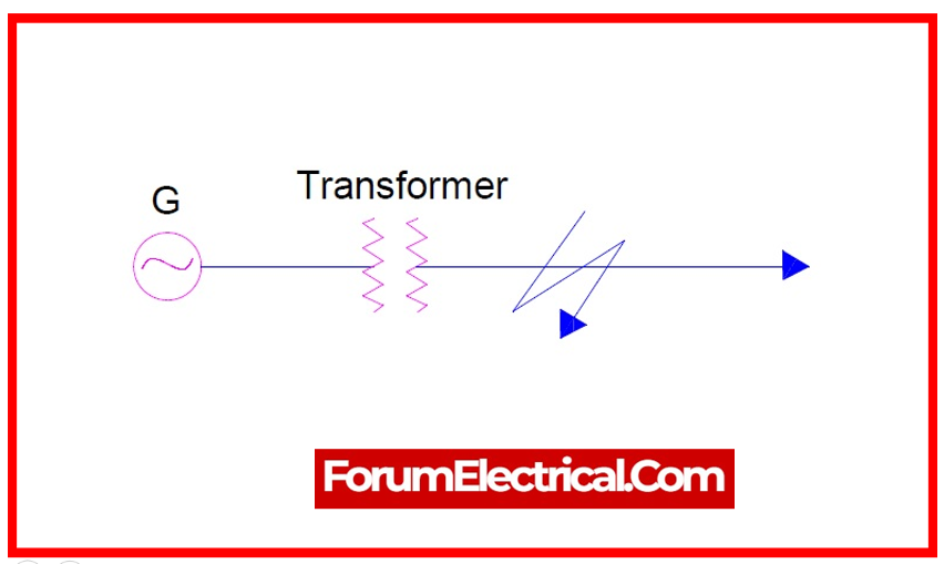
2). Generator Fault Current
The fault current in a generator differs from that in a transformer. We’ll work through an example below:
Example:
800 KW 0.8 % PF 1000 KVA 480 V 1202 FLA, what is the Fault Current (FC)?
KVA = KW / PF
KVA = 800 / 0.8 KVA = 1000
FLA = KVA / 1.732 x L-LVolts
FLA = 1000 / 1.732 x 0.48
FLA = 1202
(As shown in the table, the generator subtransient reactance (X) value is 0.16)
FC = FLA / X
FC = 1202 / 0.16
FC = 7513 A
So, a 1000 KVA generator has a far lower fault current than a 1000 KVA transformer.
The reason for this is that the impedance value at transformer & reactance value of the generator are considerably different.
Transformer: 5.75% vs. Generator: 16%.
3). System Fault Current
The MVA approach is faster and simpler than the per unit (or) ohmic methods. There is no requirement to convert to an MVA base or consider voltage levels.
This method is useful for estimating the value of the fault current. The elements must be transformed into an MVA value, and then the circuit is converted into admittance values.
Utility MVA at primary of the transformer
MVAsc = 500 MVA
Transformer Details
13.8KV – 480Y/277V
1000 KVA Transformer
Z = 5.75%
MVA Value
1 MVA = 1000KVA / 1000
MVA Value = 1 MVA / ZPU
= 1 MVA / .0575
= 17.39 MVA
Apply the admittance method to compute the fault current.
(1/Utility) MVA + (1/Trans) MVA = (1/MVAsc)
(1/500) + (1/17.39) = (1/MVAsc)
0.002 + 0.06 = (1/MVAsc)
MVAsc = 1/ (0.002 + 0.06)
MVAsc = 16.129
At 480V
FC = (MVAsc)/ (1.73 x 0.48)
FC = 16.129/0.8304
FC = 19423 KA
FC = 19423 A
How do you calculate Short Circuit Current?
The short circuit current can be calculated by first multiplying the rated full load current by 100, & then dividing the result by the actual percentage impedance of the transformer. This will give you the short circuit current.
Why do we calculate Short Circuit Current?
A short circuit analysis will help to protect persons and equipment by determining the proper interruption ratings of the protective devices (circuit breakers & fuses).
Applicable Standards
- Red Book/IEEE Standard 141: The “IEEE Recommended Practice for Electric Power Distribution for the Industrial Plants” offers instructions for calculating and analyzing short circuit current.
- IEEE 1584 Standard: Guidance on estimating short circuit currents to identify arc flash dangers in electrical systems may be found in the “IEEE Guide for Undertaking Arc-Flash Hazard Calculations”.
- ANSI/IEEE Standard 242: Short circuit current calculations are included in “IEEE Recommended Practice for Protection & Coordination of Industrial & Commercial Power Systems” in relation to protective device coordination.
- IEC 60909: “Three-Phase A.C. Systems – Part 0: Short-Circuit Currents” The IEC has published an international standard called “Calculation of currents” that offers techniques for figuring out short circuit currents in AC systems.