
- What is a DC Machine?
- Importance of DC Machines in Different Industries
- Significance of DC Machines
- Overview of DC Machine Losses
- Significance for Recognizing Losses in the DC Machines
- What is the formula for Electrical Loss?
- Different Types of Losses in DC Machines
- Electrical (or) Copper losses in DC Machine
- Magnetic Losses (or) Iron Losses (or) Core Losses in DC Machine
- Brush Losses in DC Machine
- Mechanical Losses in DC Machine
- Stray Losses in DC Machine
- Category of Losses in DC Machine
- Power Flow Diagram
- How can DC Machine Losses be minimized?
- Calculators to Determine Losses in DC Machine
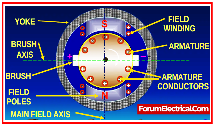
What is a DC Machine?
A Direct Current (DC) machine is an electric machine that uses direct current (DC) to either transfer
- Electrical energy into a Mechanical energy (as a Motor) or
- Mechanical energy into an Electrical energy (as a Generator).
These machines are essential in a wide range of industrial, commercial, and house applications.
Importance of DC Machines in Different Industries
- In the manufacturing industry, power machine tools provide accurate movements.
- Drive conveyors for assembly line material movement.
- In the automotive industry, strong torque at low speeds pushes electric vehicles.
- Start conventional internal combustion engine cars.
- The Renewable Energy Sector converts mechanical energy from the wind turbines into electricity.
- Use water’s kinetic energy in hydroelectric plants.
- In aerospace and aviation, operate actuators & control systems for accurate movements.
- Act as airplane auxiliary power units.
- Home Appliances: Power blenders, mixers, & food processors.
- For house comfort, run HVAC fans and blowers.
- Generators and utilities function as backup power sources for emergency systems.
- Backup power for the uninterrupted communications.
- Power robotic arms & automated machinery in the manufacturing.
- Robotic moves require precise speed & torque control.
Significance of DC Machines
Reliability: DC Motors reliable and durable.
Control: Many applications require accurate speed and torque control.
Adaptability: Function in different settings and power sources.
Overview of DC Machine Losses
There is a power loss while converting the input power to the output power. As a result, machine efficiency may be decreased.
Output Power = Input Power – Losses
The efficiency ratio is expressed as the ratio of output power to input power.
To design a high-efficiency dc machine, it is essential to understand the losses that occur in a dc machine.
The difference between the output power and the input power is referred to as the losses.
No machine is 100% efficient, and some losses always occur during the energy conversion process.
The losses increase the temperature of the equipment, lowering its efficiency. Heat energy is lost in a direct current machine.
The losses occur in the armature & field of the DC machine.
Significance for Recognizing Losses in the DC Machines
Understanding DC machine losses is essential for various reasons:
- Improved efficiency identifies and reduces losses to improve machine efficiency.
- Cost reduction reduces energy-related operational costs by optimizing designs and materials.
- Loss minimization improves application output and dependability.
- Conservation of resources support energy saving and sustainability.
- Maintenance planning identifies particular losses to predict and monitor equipment health.
- Compliance with regulations understands and manages losses to meet energy efficiency criteria.
- Technological advances promote DC machine design & operation innovations through loss research.
- Educational importance essential to electrical engineering education for potential engineers.
- Problem-solving and optimization helps to fix inefficiencies and tune machines.
What is the formula for Electrical Loss?
P (Loss) = I² R
Where,
P – Power
I – Current and
R – Resistance
This illustrates a fundamental assumption of electrical theory: increasing the voltage (V=IR) reduces line loss significantly.
Different Types of Losses in DC Machines
Losses in a DC Machine are classified into five categories & are detailed further below:
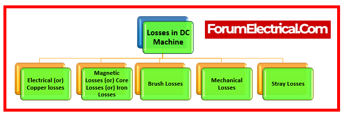
- Electrical (or) Copper losses
- Magnetic Losses (or) Core Losses (or) Iron Losses
- Brush Losses
- Mechanical Losses
- Stray Losses
Electrical (or) Copper losses in DC Machine
Electrical (or) Copper losses are referred as winding losses since the copper loss occurs due to the winding resistance.
The ohmic loss is caused by the current flowing through the windings
- Armature windings
- Field windings
Along with the armature windings and field windings, there are interpoles, and compensatory windings.
1). Copper Loss in Armature Winding
The DC machine’s armature has a very low resistance.
Armature copper losses = Ia2Ra
Where,
Ia – Armature Current and
Ra– Armature Winding Resistance
Because the load current passes through the armature winding, there is a maximum copper loss there. The copper loss in armature is roughly 25–30% of the total load loss.
2). Copper Loss in Field Winding
The field winding receives a DC supply in order to produce flux for the DC machine. The resistance of armature winding is significantly less than that of the field winding.
For this reason, even at low field current, there is a significant copper loss in the field winding.
Field winding copper losses = If2Rf
Where,
If – Field Current and
Rf – Field Winding Resistance
Around 20% – 25% percent of the DC machine’s total load loss is compensated by the field winding copper loss.
Because, the field current and field resistance in the DC machine stay almost constant, the copper loss in field winding is a nearly constant loss.
Shunt Machine: In a shunt machine, the copper loss in the shunt field is
Copper losses (Shunt) = I2shRsh
Where,
Ish-Shunt Field Current and
Rsh-Resistance of Shunt Field Windings.
Rsh contains the shunt that controls resistance.
Series Machine: In a series machine, the copper loss in the series windings is
Copper losses (Series) = I2seRse
Where,
Ise– Series Field Current and
Rse– Resistance of Series Field Windings.
Compound Machine: Both shunt and series field losses occur in a compound machine. These losses account for over 20% of the total load losses.
Interpole Windings: Copper losses in interpole windings are represented as
Copper losses (Interpole Windings) = Ia2Ri
Where,
Ri-Resistance of the Interpole Windings.
Compensating Windings: Copper loss in compensating windings, if any, is
Copper losses (Compensating Windings) = Ia2Rc
Where,
Rc– Resistance of Compensating Windings
Standards followed for electrical (or) copper losses in DC machines
IEC 60034-1: Standard methods for testing efficiency & losses in the rotating electrical machines, including DC machines.
IEEE 112: Establishes test techniques for determining the DC machine performance.
Magnetic Losses (or) Iron Losses (or) Core Losses in DC Machine
Since the armature of the DC machine rotates in a magnetic field, iron losses happen in the armature core. These losses are also known as core losses since they occur in the armature’s core.
- Hysteresis Losses&
- Eddy current losses
are the two types of iron (or) core losses.
Since the machines are typically run at a constant speed and flux density, these losses are regarded as almost constant.
Approximately 20% of the total load losses are incurred by these losses.
1). Hysteresis Loss
Hysteresis loss is the term used to describe the core loss that happens in the armature core of a DC machine as a result of magnetic field reversal in armature core as it passes under successive magnetic poles with different polarities.
The hysteresis loss can be determined using the subsequent empirical formula:
Hysteresis Loss (Ph) = kh B1.6max f V
Where,
kh– Steinmetz Hysteresis Coefficient
Bmax-Maximum Flux Density,
f -Magnetic Reversal Frequency
V – Armature Core Volume
By using materials like silicon steel for the armature core, which have a low value of Steinmetz’s hysteresis coefficient, the hysteresis loss in the DC machines can be significantly decreased.
2). Eddy Current Loss
An electromagnetic field (EMF) is created in the armature core of a DC machine when it rotates in magnetic field of the poles, causing eddy currents to flow through it.
Eddy current loss is the term for the power loss carried on by these eddy currents. The eddy current loss can be determined using the subsequent empirical formula:
Eddy Current Loss (Pe) = ke B2max f2 t2 V
Where,
Ke– Proportionality Constant
Bmax-Maximum Flux Density,
f -Magnetic Reversal Frequency
t – Lamination Thickness
V – Armature Core Volume
It is clear from the eddy current loss equation that the eddy current loss is dependent on the square of the lamination thickness.
Thus, the armature core is constructed from thin laminations separated from one another by a thin varnish layer in order to minimize this loss.
Standards followed for core losses in DC machines
IEC 60034-1: Includes techniques for calculating DC machine core losses.
Brush Losses in DC Machine
The DC machine’s revolving armature is powered by brushes, which deliver DC current to the rotating component.
The contact resistance between both commutator surface and the brush contacting area should ideally be zero. Zero contact resistance is not achievable in practice, unfortunately.
The carbon brushes experience a voltage decrease. The voltage drops across the brush & armature current determine the brush power drop.
The losses that occur between the carbon brushes and the commutator are referred to as brush losses.
At the brush contact point, there is a power loss. The armature current(Ia) and the brush contact voltage drop determine the brush drop. The following equation provides it as follows:
Power Drop in Brush (PBD) =VBDIa
Where,
PBD – Power drop in Carbon Brush
VBD – Voltage Drop in Carbon Brush
Ia – Armature Current
Over a wide range of armature currents, the voltage drop across a set of brushes is roughly constant.
NOTE: It is typically assumed that the brush voltage loss is approximately 2 volts if the value is not stated. The brush drop loss is therefore calculated as 2Ia.
The brush power loss is included in the DC machine’s armature copper loss and cannot be calculated separately.
Mechanical Losses in DC Machine
Mechanical losses are those that occur as a result of machine mechanical effects.
Mechanical losses are proportional to machine speed. However, for a given speed, these losses are nearly constant.
Mechanical losses are classified as
- Friction Loss and
- Windage Loss
1). Friction Loss
Friction loss occurs in a DC machine in the form of brush friction, bearing friction and so on.
As a result of friction across the inner cage and the outer cage of the bearing, the bearing experiences a loss of energy in the form of heat.
2). Windage Loss
Windage losses are the losses that occur in the machine’s moving parts & the air inside the machine. These are insignificant losses.
These losses constitute around 10 to 20% of the total full load losses.
Standards followed for mechanical losses in DC machines
IEC 60034-2-1: Addresses the mechanical vibration of specific electrical machinery that rotate.
IEEE 115: Provides specifications for electrical machines’ mechanical parts.
Stray Losses in DC Machine
These are categorized as miscellaneous losses. Stray load losses take consideration of the following factors:
- The flux distortion caused by the armature reaction.
- Short circuit currents in coil when it commutates.
These losses are extremely difficult to calculate. As a result, an acceptable value for the stray loss must be assigned.
Stray losses are often assumed to represent 1% of full load output power for most devices.
They are mainly caused by inaccuracies in the machine’s design and modeling.
NOTE:Iron (or) core losses & mechanical losses are referred to collectively as stray losses.
Standards followed for stray losses in DC machines
IEEE 62: Electrical machinery stray load losses is the primary concern.
Category of Losses in DC Machine
Within the field of DC machines, it is possible to categorize the losses that have been discussed above into two different categories:
- Constant Losses
- Variable Losses
Total losses in a DC machine = Constant losses + Variable losses
1). Constant Losses
Constant losses are those losses in DC machine that are constant at all loads.
- Iron losses,
- Shunt field copper losses, and
- Mechanical losses
are examples of these losses.
2). Variable Losses
Variable losses are those losses in DC machine that vary with the load. A DC machine’s variable losses are
- Armature copper losses and
- Series field copper losses
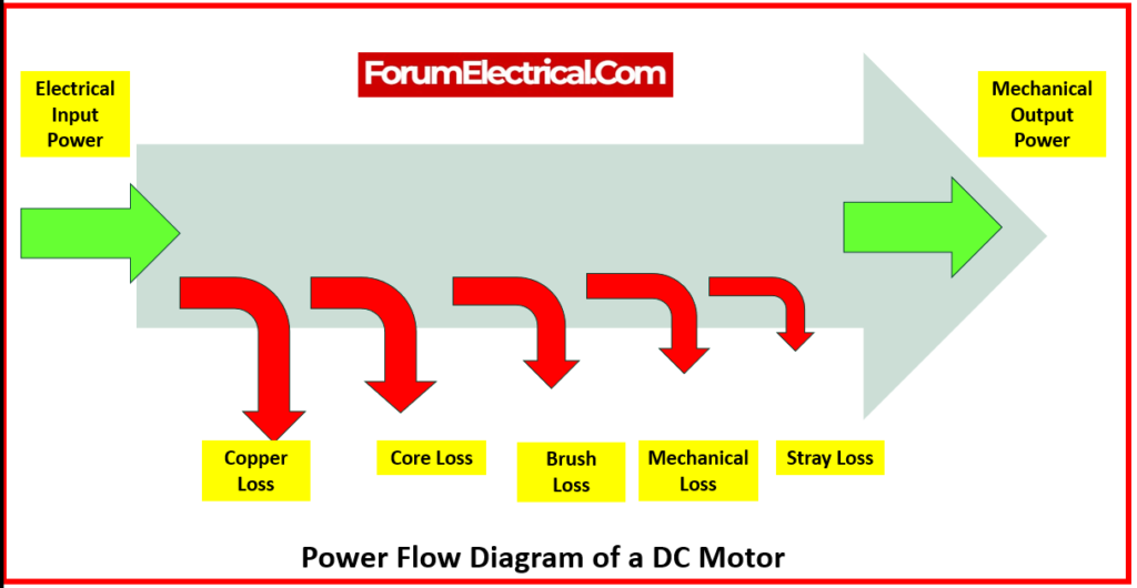
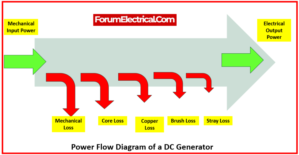
Power Flow Diagram
The power flow diagram is the most practical way to better understand the losses that occur in a DC motor or generator.
The diagram shows how much power has been lost due to different types of losses as well as how much power has actually been transformed into the output.
The standard power flow diagrams for a
- DC Motor and
- DC Generator
are shown below:
How can DC Machine Losses be minimized?
DC machines are primarily affected by losses that originate from three different sources, namely
- Switching sources,
- Magnetic sources, and
- Resistive sources.
Covering the magnetic core will prevent eddy currents from flowing through it, which will result in a reduction in magnetic and hysteresis losses.
Because the size of the wire and the insulation thickness are important in filling the cross-sectional area with wire, resistive losses can be avoided by careful design.
Calculators to Determine Losses in DC Machine
Determine DC machine losses accurately and with ease by utilization of specialized calculators.
By carefully evaluating mechanical, stray, ferrous, and copper load losses, these tools support the optimization of efficiency.
Examine their features, which allow engineers to recognize, measure, and reduce losses, assuring improved machine efficiency and energy savings.